Category: Articles

Drones for Façade Inspections- Feb 2023

Drones for Façade Inspections

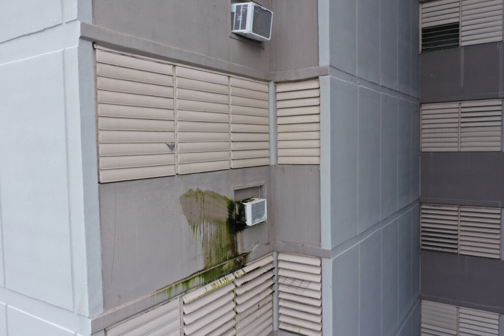
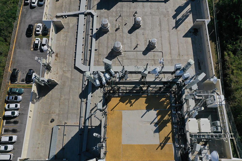
Drones have changed our world in a myriad of ways. For engineers and façade professionals, drones have altered how they evaluate building facades, minimizing time and expense in the field and allowing more time for study and evaluation. Typically, a drone can capture detailed photos and videos of a multi-story tower façade in less than an 8-hour day.     

Advantages of drones for façade inspections

First and foremost, using drones for façade inspections saves time and money. Pre-drones, inspections required equipment ranging from a ladder to an aerial lift or even scaffolding. Depending upon the height of the building, inspection could take several hours to several days. Drones allow experts to conduct a visual to inspection  either while the drone is in flight or soon after, while viewing the photographs or videos. Once review of the photographs is completed, the expert can decide whether a hands-on inspection is required or if the photographs provide enough detail to make a determination.  

Safety is another advantage to drones. During any aerial operation on either scaffolding or in an aerial lift, the experts performing the inspection will typically need some sort of training, in addition the appropriate PPE. These aerial operations come with a variety of potential safety hazards including contact with live wires, falls from heights, top overs/collapses, objects falling from lifts, and many more. 

Drones can produce highly detailed photographs and videos. Many drones on the market today have cameras capable of taking 20MP or better still shots and 4k or better videos. In addition, most drone cameras contain gimbals (stabilizers) allowing vertical from -90° (straight down) to 20° (above horizontal), allowing the camera to get angles looking down and up on the façade.

Using Drones on Façade Inspections

Drones have many limitations, including where and at which altitude they can fly.   The FAA publishes near-real time airspace authorizations on the UAS Facility Maps website.   This provides maximum altitudes around airports where the FAA may authorize Part 107 operations and still requires the pilot to request a waiver to fly in these areas.  Additionally, there are limitations about flying over people and moving vehicles, so the areas around the structure may have limited access.

Resident notifications: People can be easily spooked by drones, so it is imperative that the building management provide proper notification to residents and tenants of the structure(s).   

Weather conditions: Wind can always have an impact on drones, but this is especially important on multi-story structures.  Wind speed tends to increase with height above the ground. As wind hits the side of a building, it has nowhere else to go and is pushed, up, down, and around the sides. These wind forces can cause instability in drones if not properly managed.

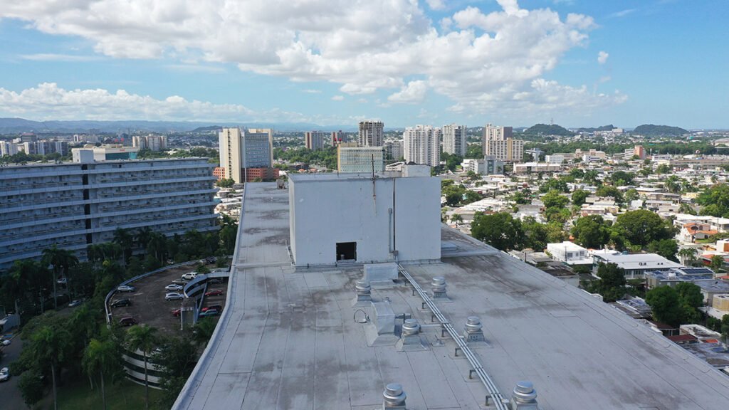
Using High Quality 4k drones on our inspections has been an extremely valuable tool for Haag during inspections. The ability to see tower facades and their roofs from a higher perspective enables us to evaluate from different angles, and helps us feel confident when determining causation. Over the past 6 years, the use of 4k Drones  to inspect high density towers has changed the way inspections are performed”, said Brandon Alaniz, Principal Consultant with Haag Construction Consulting.  “We now have the acute ability to review surfaces at higher elevation to assist us with determining a final scope of repair for our clients. The camera resolutions have the capability for us to review surfaces at a granular level from hundreds of feet in the air. These drones tell us a story from an overall perspective. It’s enabled us to provide wonderfully detailed presentations for our clients. We believe as the technology continues to develop, drones will become part of the standard operating procedures for all assignments.” 

Key Considerations

  • Flight Regulations:   Follow FAA and company policies and procedures.  Obtain waivers where necessary.
  • Resident/Tenant Notifications:  Require management to provide notifications
  • Flight area walkaround:  Typical with any flight, but especially on multi-story buildings it is imperative to know that area you will be flying in locating trees, utility lines, other structures, building appurtenances, balconies, and other features that could impact your flight. 
  • Securing area under the drone:  In most cases, the FAA prohibits drones from flying directly over people.  It is critical to work with your visual observer to secure an area under the drone, as it moves along the façade to ensure compliance with this requirement. 
  • Weather considerations:  Wind speeds, not only at ground level, but at or near the building’s rooftop.
  • Aviation Insurance:  Drones, since they are FAA registered aircraft, are typically not covered under most insurance policies and need separate aviation insurance.    
  • Battery management:  Depending upon the size of the building, going through multiple batteries is a possibility.  This requires the pilot to have multiple batteries and chargers, in addition to finding adequate power supply on or around the site.
  • Pilot management: Looking up at the drone or down at the screen for an extended period of time can cause fatigue.  Establishing a procedure for pilot management (Fly through 2 batteries and take a 30-minute break) is key
  • Visual Observer:  A visual observer is critical to give the pilot a second set of eyes on the drone in the event of wind bursts that could shift the drone towards the building or other structures or in the event pedestrians enter the area adjacent to the drone.

For more information about drones and façade inspections, please reach out to Kevin Kianka, Operations Manager, Technical Services, or Brandon Alaniz, Principal Construction Consultant.

Authors

Kevin Kianka, P.E., DIRECTOR OF Operations, Technical Services

Kevin Kianka, P.E., serves the Director of Operations, based in Haag’s Sugar Land (Houston), TX office and leading Haag Technical Services efforts nationwide, including all services related to 3D Laser Scanning, 3D Modeling, Drones (sUAV’s), GIS, and other advanced technologies.

A licensed Professional Engineer in Texas, New Mexico, Colorado, New Jersey, New York, Pennsylvania and Florida, Mr. Kianka obtained a Bachelor of Science in Civil Engineering from Drexel University (Philadelphia, PA) and has over 15 years of experience in the field of Engineering.  His work has included bridge and structural design, NBIS (Bridge) inspections, highway and roadway design, land development and site design, stormwater design and management, zoning analysis and 3D documentation, drones (sUAV’s), GIS, and as-built modeling.  Since 2008, he has focused on 3D documentation and the completion of Engineering Surveys to assist in the design, investigation and coordination of engineering projects.  Mr. Kianka utilizes his design and documentation experience to oversee the 3D Documentation and creation of 3D models, visualization and animations for all projects that Haag completes.

Mr. Kianka oversees Haag’s drone program and maintains a Remote Pilot Certificate – sUAS Rating with the FAA. He is a Director of the US Institute of Building Documentation (USIBD), and is a subcommittee member for ASME B30.32 committee preparing consensus documented related to Unmanned Aircraft Systems used in Inspection, Testing, Maintenance, and Lifting Operations for Cranes.

brandon alaniz, PRINCIPAL Construction Consultant

Brandon Alaniz is a Principal Construction Consultant with Haag Construction Consulting Co. He is an experienced construction consultant with more than 15 years in the construction industry. He is responsible for maintenance, and completion of all consulting services and related work product. His emphasis is building reconstruction, restoration, equipment and machinery cost, and remediation cost for the insurance industry.

Mr. Alaniz prepares construction loss and restoration estimates. He oversees remediation management services for losses that will be either repaired by the owners and need constant supervision to expedite, or losses that require management to fast-track a project without the need of a general contractor. Mr. Alaniz works to ensure the favorable and equitable conclusion of a loss. His experience includes many types of construction and restoration including: multi-family dwellings, commercial buildings, industrial complexes, and institutional facilities (schools, hospitals, municipal). 


Any opinions expressed herein are those of the author(s) and do not necessarily reflect those of Haag Technical Services, Haag Engineering Co., Haag Education, or parent company, Haag Global, Inc.

Effects of Hail-Caused Dents on the Thermal Performance of Insulation Under Single-Ply Roofing

Effects of Hail-Caused Dents on the Thermal Performance of Insulation under Single-Ply Roofing

Haag Research & Testing recently published an intriguing study in the International Institute of Building Enclosure Consultants (IIBEC)’s Interface Magazine– Effects of Hail-Caused Dents on the Thermal Performance of Insulation Under Single-Ply Roofing. This article examined whether, and by how much, hail dents would affect the R-value of a roof’s insulation. Could a property owner see a noticeable difference in their energy bills due to changes in insulation?

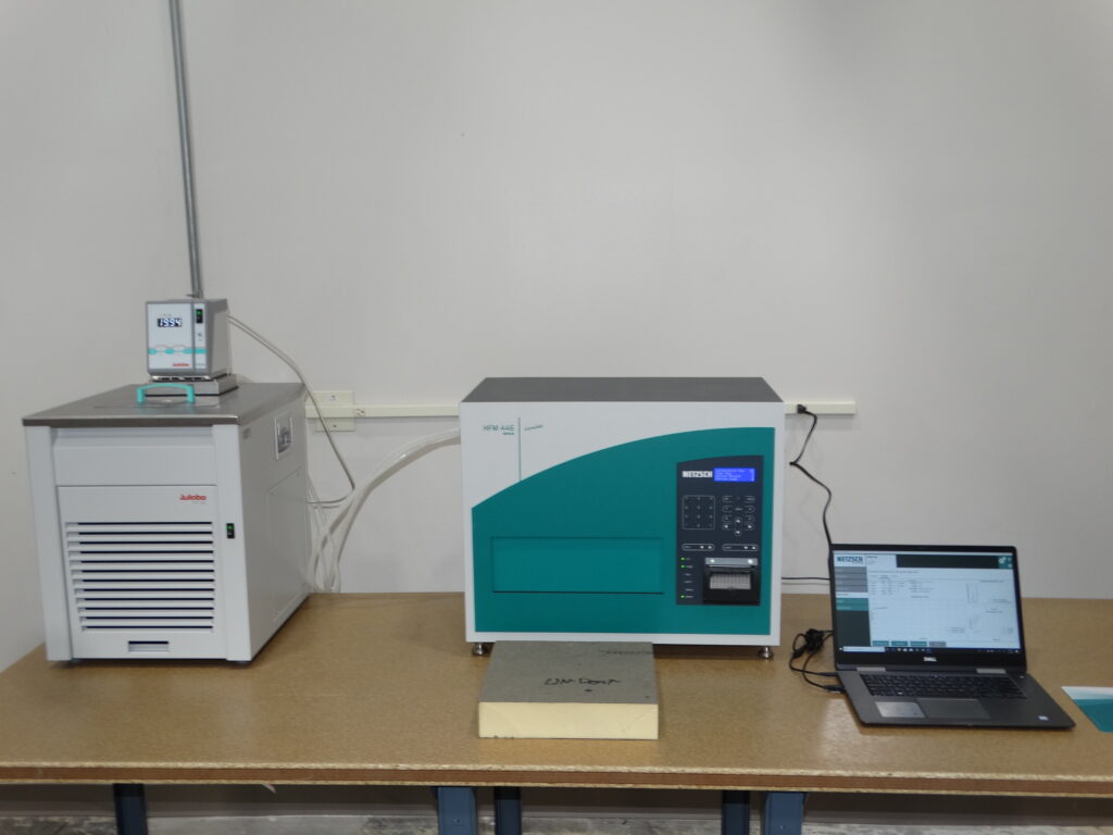
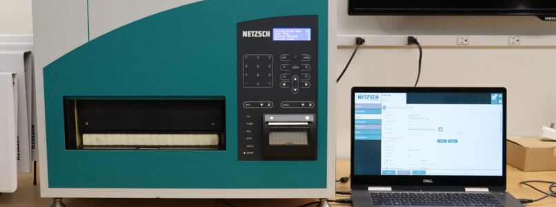
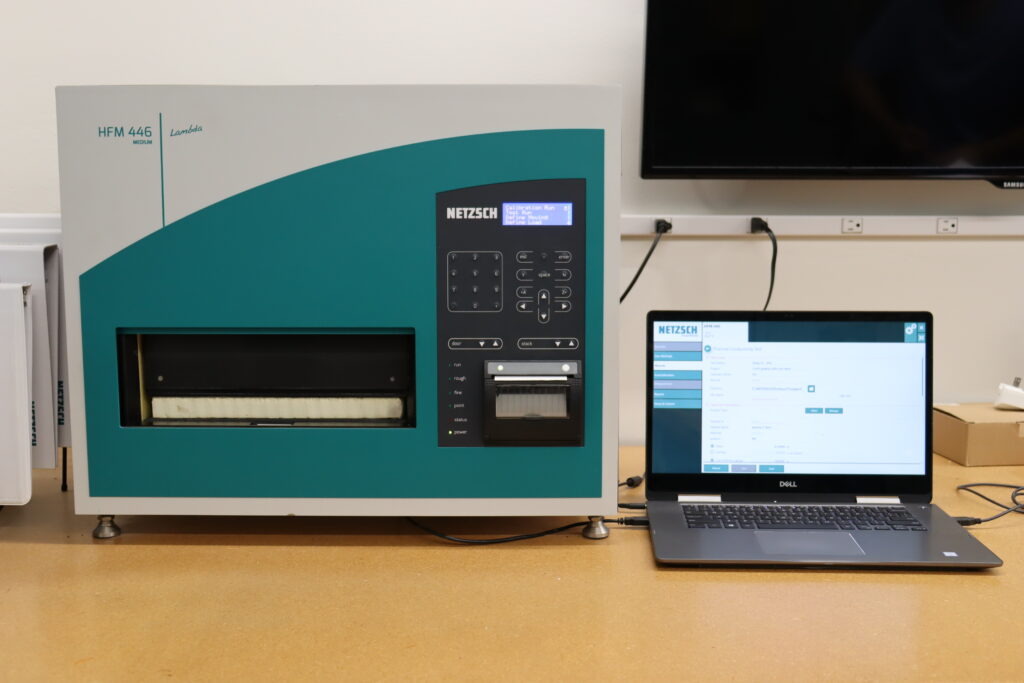
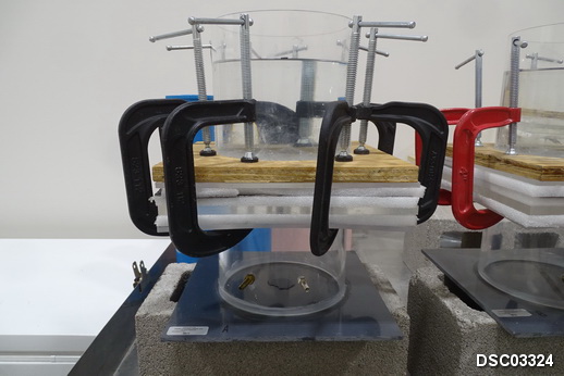
To conduct our testing, Haag used a heat flow meter (HFM) to evaluate the thermal performance of roof insulation and measured the thermal resistance to conductive heat flow (R-value). We measured the thermal resistance of insulation in several dented configurations, and compared those to samples without dents to determine if the dents resulted in a measurable loss of R-value.

Read Effects of Hail-Caused Dents on the Thermal Performance of Insulation Under Single-Ply Roofing, which appeared in the December 2022 issue of IIBEC Interface article here. Written by Steve Smith, P.E., Robert Danielson, P.E., and Cory Hurtubise, EIT. 

Haag Research & Testing’s IAS-accredited laboratory performs various tests that consultants, adjusters, roofing contractors, public adjusters, and manufacturers rely for analysis of roofing samples. Visit HaagResearchTesting.com to learn more and view our testing in action.  

Heat Flow Meter
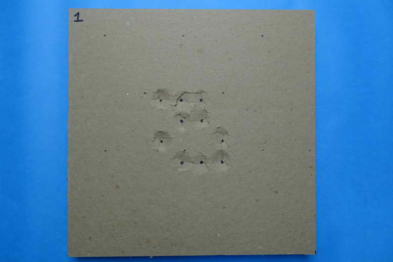
Example of dents in polyisocyanurate insulation
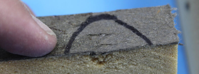
Close-up at dent profile.

Author

Steve Smith, P.E., Director of Research & Testing, Principal Engineer

Steven R. Smith is a Forensic Engineer with Haag Engineering Co., and the Director of Research & Testing. Mr. Smith is an experienced forensic engineer who began his career with Haag more than 24 years ago. He spent seven years working as a Senior Lab Technician while earning a Bachelor of Science in Mechanical Engineering degree from The University of Texas at Arlington. He has been involved with the lab throughout his career, and has been able to leverage his extensive and practical engineering field experience with research and testing projects.

Mr. Smith’s areas of expertise include accident reconstruction, mechanical equipment evaluations, code and standards compliance, roofing system evaluations, and fires and explosions. He is a licensed Professional Engineer in Arkansas, Minnesota, Missouri, Oklahoma, Texas, and Wisconsin. He is a member of the American Society of Mechanical Engineers (ASME), Society of Automotive Engineers (SAE), and Pi Tau Sigma National Honor Society. Prior to joining Haag, Mr. Smith was a Petty Officer Second Class in the United States Navy. He trained at the Navy Nuclear Power Training Command Center in Orlando Florida and was stationed on the USS Arkansas (CGN-41), where he maintained reactor and steam plant chemistry, performed radiological controls, and operated mechanical equipment in the propulsion plant.


Any opinions expressed herein are those of the author(s) and do not necessarily reflect those of Haag Technical Services, Haag Engineering Co., Haag Education, or parent company, Haag Global, Inc.

Laboratory Testing of Roofing Samples, Nov. 2022

Laboratory Testing of roofing samples

Steve Smith, P.E., Director of Research and Testing, Principal Engineer

Art is in the eye of the beholder. One person can look at a painting of an apple tree and clearly see the arc of human history portrayed from the deep roots to the solid trunk rising from the ground, to the fruits of technological advancement in the bright shiny apples hanging from the limbs. Another peers at the same painting and sees the sun and the earth working in harmony to produce life giving food for humanity. Someone else observes the magnificent artwork and sees a tree.

Although it may be entertaining to view artwork and try to determine the true meaning or purpose of the piece, you don’t want to hire a roof consultant only to receive an ambiguous report that relies on your own subjectivity to discern their conclusions. If you had only taken roofing samples and sent them to an accredited laboratory that specializes in providing the concrete answers you seek.

Haag Research & Testing is an accredited testing laboratory that specializes in analysis of roofing samples and can provide answers to the following questions.

  • Was the condition on the sample related to hailstone impact?
  • What size of hail can damage the sample?
  • Does the damage extend through the sample or is just the coating damaged?
  • What wind speed would it take to displace these roofing tiles?
  • Did hail-caused dents in the insulation reduce the R-value?
  • Does water leak through a particular feature in the sample?

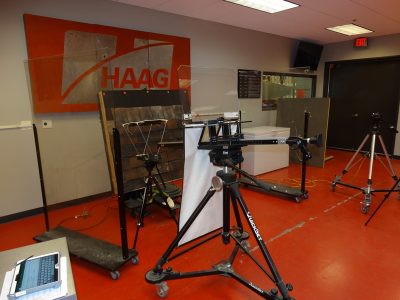
Our laboratory performs various tests that Haag Engineers have relied on for decades either for developing information used in research papers or for giving specific information on active assignments. The Haag laboratory also performs tests for non-Haag consultants, adjusters, roofing contractors, public adjusters, and manufacturers. Brief descriptions of some of our more popular tests are provided below. You may also visit our website at HaagResearchTesting.com to learn more and to watch testing videos. 

Overview of test setup with Haag IBL-7 ice ball launcher.
impact testing

Frozen solid ice balls are propelled at samples to simulate the effects of hailstone impacts. We use a wide range of ice ball sizes from 1/2 inch to 4 inches in diameter, which allows us to examine the effects of very small hail up to massive hail that can damage most roofing types. Test panels are constructed to replicate as-installed conditions and are typically impacted by simulated hailstones at 90-degree angles to replicate worst case conditions. We can vary the speed and angle of impact as needed. Learn more. 


Desaturation Testing

Bituminous roofing products, including asphalt built-up roofing (ABUR), modified bitumen (mod-bit) roofing, and asphalt shingles are subjected to hot solvent that dissolved the asphalt, allowing the sample reinforcements to be examined for conditions related to impact-caused damage. Learn more. 


single-ply analysis

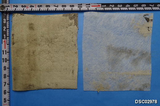
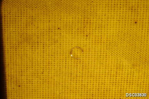
Single-ply roofing products, including polyvinyl-chloride (PVC), thermoplastic polyolefin (TPO), ethylene propylene diene terpolymer (EPDM), and others are examined visually, tactilely, microscopically, and using back-lighting techniques to determine if there are fractures in the membranes associated with impact forces. Learn more. 

View of panel after Test 5.
Wind Simulation

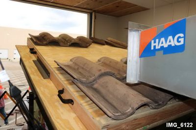
Test panels are constructed in a manner to simulate the as-installed conditions of roofs covered with shingles, tiles, shakes, slates, or synthetic products. Panels are set at a predetermined angle and wind is blown onto the panels to determine the approximate wind speed it takes to lift, displace, or otherwise damage the product. Various configurations can be evaluated to provide a wide range of possible scenarios. Learn more.

r-Value

The thermal resistance of insulation is measured, and comparisons made between samples with and without hail-caused dents to determine if hail-caused dents resulted in a measurable loss of R-value. Learn more. 

Water Column

Samples containing suspected impact-caused conditions, including displaced surfacing, dents, cracks, etc. are subjected to 6 inches of water and then monitored over a 7-day period. Air pressure cycles are conducted following the 7-day period (with the water still in place) to determine if the roofing sample will leak. Learn more.

Author

Steve Smith, P.E., Director of Research & Testing, Principal Engineer

Steven R. Smith is a Forensic Engineer with Haag Engineering Co., and the Director of Research & Testing. Mr. Smith is an experienced forensic engineer who began his career with Haag more than 24 years ago. He spent seven years working as a Senior Lab Technician while earning a Bachelor of Science in Mechanical Engineering degree from The University of Texas at Arlington. He has been involved with the lab throughout his career, and has been able to leverage his extensive and practical engineering field experience with research and testing projects.

Mr. Smiths areas of expertise include accident reconstruction, mechanical equipment evaluations, code and standards compliance, roofing system evaluations, and fires and explosions. He is a licensed Professional Engineer in Arkansas, Minnesota, Missouri, Oklahoma, Texas, and Wisconsin. He is a member of the American Society of Mechanical Engineers (ASME), Society of Automotive Engineers (SAE), and Pi Tau Sigma National Honor Society. Prior to joining Haag, Mr. Smith was a Petty Officer Second Class in the United States Navy. He trained at the Navy Nuclear Power Training Command Center in Orlando Florida and was stationed on the USS Arkansas (CGN-41), where he maintained reactor and steam plant chemistry, performed radiological controls, and operated mechanical equipment in the propulsion plant.


Any opinions expressed herein are those of the author(s) and do not necessarily reflect those of Haag Technical Services, Haag Engineering Co., Haag Education, or parent company, Haag Global, Inc.

Visualizing the Unseen: Modern Premises Liability Analysis, Oct. 2022

VISUALIZING THE UNSEEN:  MODERN PREMISES LIABILITY ANALYSIS

Christopher DeSantis, RA, AIA, CXLT and Benjamin T. Irwin, PE, DFE, CXLT

At its core, forensic architecture and forensic engineering can simply be thought of as the application of facts and science in answering technical questions posed by a lay audience.  Similarly, premises liability evaluation can simply be thought of as a technical evaluation of the interactions between human beings and the constructed environment around them, in response to a specific incident where a specific constructed condition is alleged to have caused injury to a specific person.  Seems simple, right?

  • Step 1:  Analyze the facts.
  • Step 2:  Apply the science(s) to the facts.

Traditionally, premises liability analysis has focused largely on compliance of the constructed conditions with codes and industry norms.  Again, simple right?

  • Step 1:  Determine the applicable codes and industry norms.
  • Step 2:  Evaluate compliance of the constructed conditions.
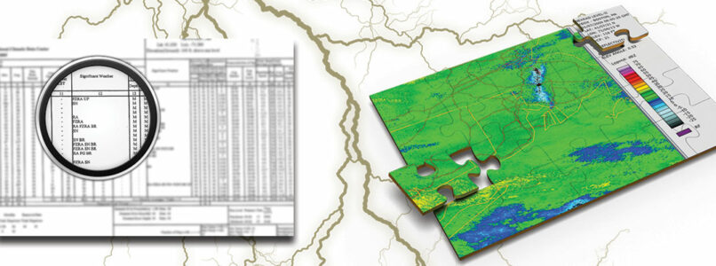
Re-assembled jigsaw pieces

But what happens when the facts are unclear, or even partially contradictory?  What if the facts are unknown?  Similarly, how do you analyze compliance, if you can’t determine the age of the constructed conditions?  These answers require a more modern, multi-faceted, and multi-disciplinary approach.

We can start with a simple idea:

Nearly everything leaves evidence somewhere, and there are many more opportunities to technically investigate a given fact pattern now than there have ever been before.

This is modern premises liability analysis, where the key is to reconstruct a given incident to the greatest extent possible, either physically in reality, in a virtual manner, or in some combination of the two.  When an incident can be better visualized, even if the conditions have since changed, it can become much simpler to see the facts, codes, standards, and science more clearly.

Consider being faced with a fact pattern involving a fall event on a roadway construction site, where the construction site is long gone.  There were no witnesses to the incident, limited photos from the time of the incident, and the available testimony created a he-said, she-said situation that didn’t seem to make sense in the context of the other available information.  A new first step is needed, to verify the facts before analyzing them.


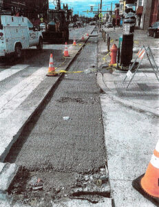
Limited construction zone protection after the incident.
Photo from the time of the incident, with limited foreground information, but broader background information.

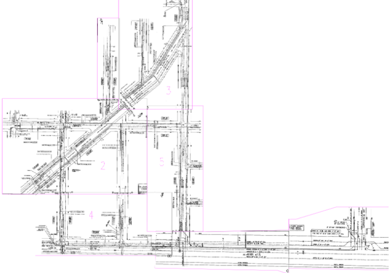
As a part of this fact pattern, construction staging plans were provided piecemeal and in an incomplete manner, along with out-of-sequence and partially missing/redundant daily field logs.  Re-assembling these jigsaw pieces, revealed verifiable extents of the construction zone on the date of the incident, including what construction equipment was on site at the time of the incident.  It also revealed the adjacent streets on which the same contractor had performed similar work.

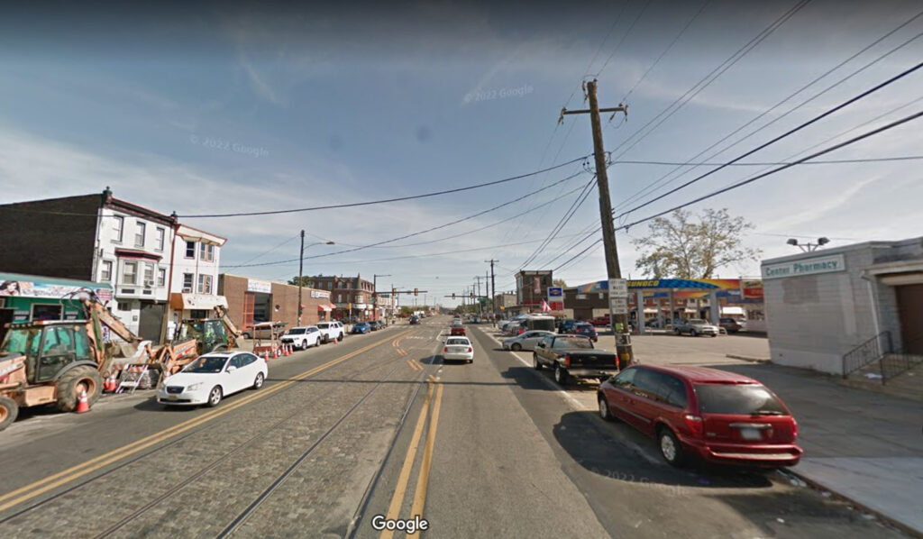
While the dated street level imagery did not indicate the exact conditions present within the construction zone at the time of the incident, it did indicate the construction zone protection methods utilized by the contractor elsewhere on the same project on the adjacent streets.  A repetitive pattern of construction zone protection emerged that aligned with only one portion of the testimony, but not the other.  Certain elements of the same repetitive pattern were also evident in the limited photos taken from the time of the incident.

The dated street level imagery near the construction zone showed limited construction equipment, surrounded by limited construction zone protection, which more closely aligned with the contradictory testimony, but was actually from a different point in time.  Combining all of this evidence using a multi-faceted approach, the conditions actually present at the time of the incident were reconstructed, such that these unseen conditions could be visualized clearly utilizing verifiable facts.

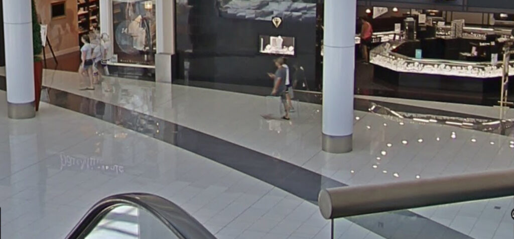
It is not always this complicated, though.  Sometimes, a simple review and enhancement of the video surveillance footage from an incident will provide the fact verification needed.  There are also now some interior street level images being recorded inside of buildings.  Both of these modern technologies can also be used as part of a multi-disciplinary premises liability evaluation approach, revealing details that could not be easily seen before.

Post-incident conditions
Pre-incident conditions shown in interior street level image.

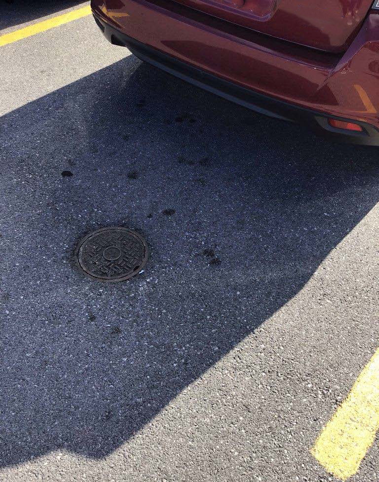
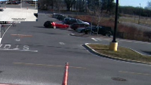
Consider another example, one where the video surveillance footage brought confusion, rather than clarity.  This basic fact pattern suggested that the wrong incident location was investigated by a property owner after an incident had occurred at a known location somewhere else.  The video surveillance footage captured the incident in a verifiable location, as well as the investigation conducted at that same location, but the car shown in the photos from the investigation didn’t match the car allegedly present at the time of the incident.  So, what created this discrepancy?

Photo from the time of the incident, allegedly showing the wrong car.
Enhanced video showing a change in the car parked next to the incident location between the time of the incident and the time of the investigation.

The key to understanding what happened was to visualize the conditions present at the different points in time, as viewed from the perspectives of the different parties at those different times.  Some constructed environments are dynamic in nature, with conditions that change frequently.  Combining review and enhancement from all of the video surveillance footage (not just the two segments referenced earlier), with review of the designed site features, in combination with in-field measurements, along with analysis of the changes in the dynamic environment over time, the conditions present at the time of the incident could again be reconstructed virtually, making the unseen clear to visualize.

In each case, the early preservation of evidence was key.  Early engagement of experts can also help to bring clarity to additional unseen, but verifiable, facts early on in the claims and/or litigation processes, improving the potential for early, informed decision-making.  The evidence is often out there somewhere, and our task, together, is to locate, verify, and analyze it in a multi-faceted manner, utilizing our arsenal of modern tools.  

What can we bring into clearer focus for you?

Authors

Christopher DeSantis is an accomplished and credentialed Architect with a solid career record of innovative and outstanding architectural design. Prior to joining Haag, Christopher worked as an architect, collaborating with structural engineers in design and preparation of project details, wall sections, and construction documents. He conducted detailed forensic investigations and structural integrity inspections, documented in field reports, in addition to performing contract administration and working as project manager for multiple projects. He also worked as a Graduate Teaching Assistant, an intern/builder at SouthCoast DesignBuild, and as a construction laborer and mason. His project experience includes investigation and restoration of multiple school campuses and commercial buildings. He has designed many large condominium projects, multi-use developments, government buildings, retail and restaurants, and commercial buildings.

Benjamin T. Irwin is a Forensic Engineer with Haag Engineering Co. With dual degrees in architecture and civil engineering from Lehigh University, and over 20 years of diverse professional experience, Mr. Irwin provides a wide array of engineering, design, construction, and safety consulting and expert witness litigation support services.  He is a registered Professional Engineer (P.E.) in 23 jurisdictions and is recognized as a Model Law Engineer (MLE) by the National Council of Examiners for Engineering and Surveying (NCEES).  He is also a Board-certified Senior Member of the National Academy of Forensic Engineers (NAFE), holding the designation of Diplomate Forensic Engineer (DFE).  He had been qualified for, and testified within, local, state and Federal courts, with retentions from both plaintiffs and defendants.


Any opinions expressed herein are those of the author(s) and do not necessarily reflect those of Haag Technical Services, Haag Engineering Co., Haag Education, or parent company, Haag Global, Inc.

Real-Time, Interactive Storm Data: Haag Hurricane GeoPortal, Sept. 2022

HURRICANE GEOPORTAL: real-time, INTERACTIVE storm data

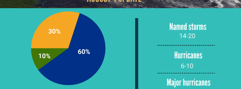
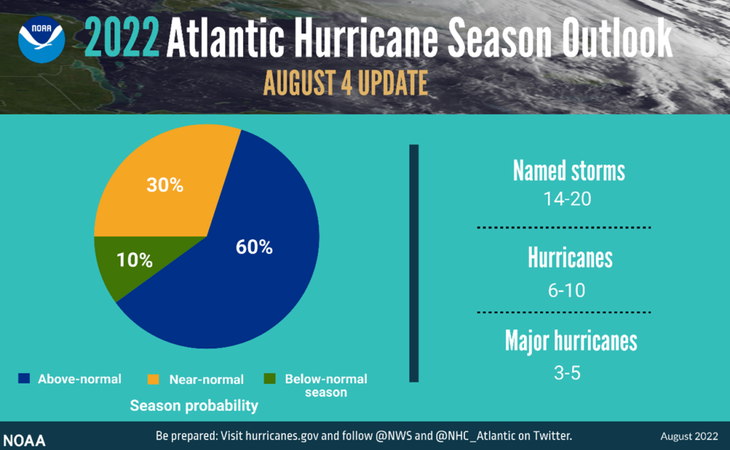
According to the National Oceanic and Atmospheric Administration’s (NOAA) annual mid-season update issued by the Climate Prediction Center, atmospheric and oceanic conditions still favor an above-normal 2022 Atlantic hurricane season. NOAA’s update to the 2022 outlook — which covers the entire six-month hurricane season that ends on November 30th — calls for 14-20 named storms (winds of 39 mph or greater), of which 6-10 could become hurricanes (winds of 74 mph or greater). Of those, 3-5 could become major hurricanes (winds of 111 mph or greater). NOAA provides these ranges with a 70% confidence.

The updated 2022 Atlantic hurricane season probability and number of named storms.

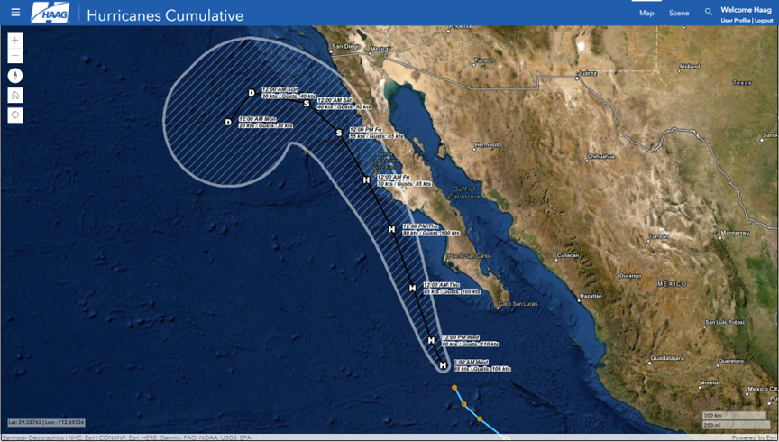
Considering this outlook for 2022 as well as very active recent hurricane seasons, it is imperative for businesses and individuals to have quick and reliable access to key data points. Haag believes that there is no such thing as too much data if the data is organized, relevant, and easy to access. The Haag Hurricane Geoportal checks these boxes and much more. It gives power to the user to view multiple datasets, interact with the data, and decide which information is most valuable to them. The Haag Hurricane Geoportal utilizes a map-based interface to provide on-demand access to several useful data sources including:

  • Real-time data for active and recent storms from the current hurricane season
  • Detailed storm data from the past three hurricane seasons with options to filter data based on storm name
  • Wind speeds and pressure at observed positions along a storm’s path
  • Direct access to official National Hurricane Center (NHC) storm reports
  • Radar and aerial imagery data for storms
  • Access to local climatological data reports
  • NEXRAD radar mosaics for current and past storms
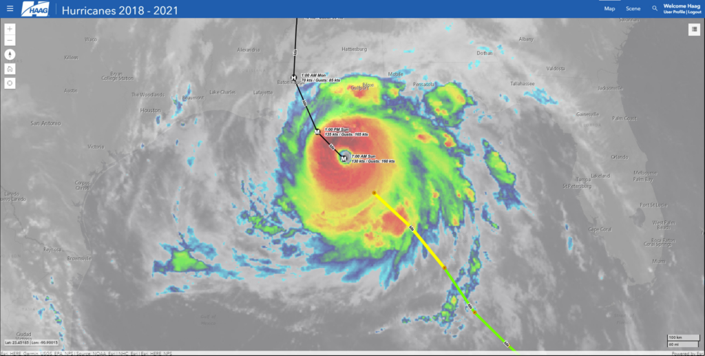
Satellite imagery, observed track and positions, forecasted track and positions of Hurricane Ida, August 2021.
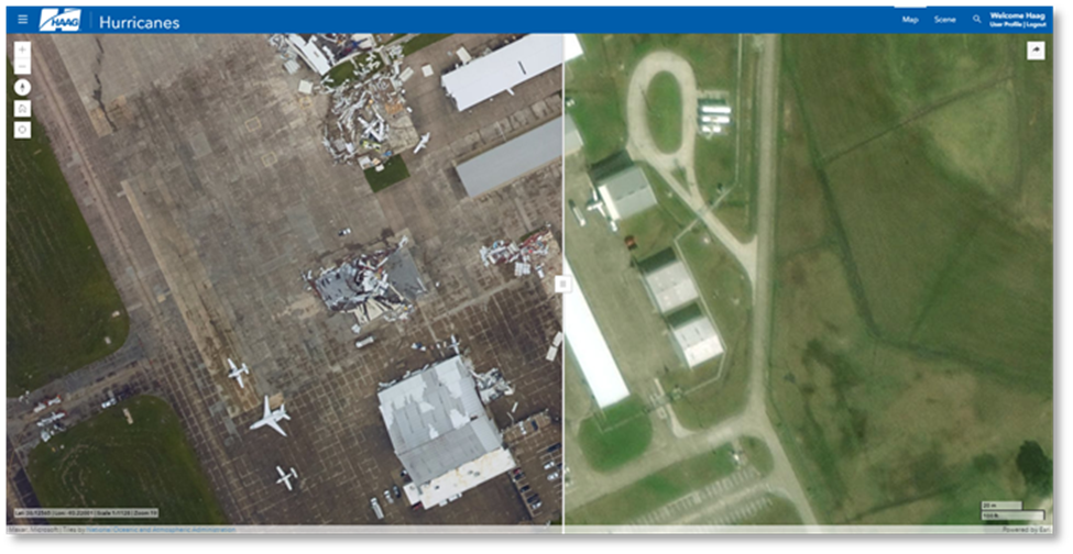
Before and after aerial imagery showing damages caused by Hurricane Laura, August 2020.

The Haag Hurricane Geoportal provides timely access to reliable data in one easy-to-use platform. While we can’t stop severe weather from happening, we can create tools to help make proactive planning and recovery much easier. The Hurricane Geoportal is your one-stop shop for keeping an eye on the data for the eye of the storm.

If you would like to learn more about the Haag Hurricane Geoportal, please contact Marcie Deffenbaugh, GIS Services Manager, to view a demo or for more information. Haag’s Hurricane Geoportal is available via subscription– one year subscription for $50/month or opt for a month-to-month subscription for $75/month.

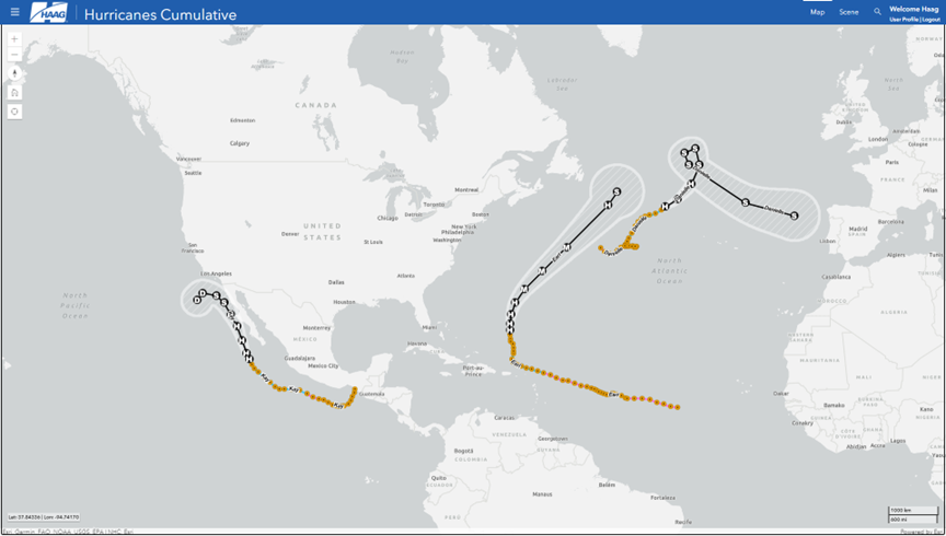
View of observed tracks and positions, as well as forecasted tracks, positions, and error cones of active storms as of 10:00 AM EST on 9/7/2022.
View of Hurricane Kay with forecasted track, position, and error cone as of 10:00 AM EST on 9/7/2022.

Marcie Deffenbaugh is the Manager of GIS Services for Haag Technical Services, a division of Haag Global, Inc.  In this role, Ms. Deffenbaugh oversees initiatives related to GIS planning, system design, and system administration. She also manages a staff of GIS technicians, analysts, cartographers, and project administrative assistants who provide data validation and project management services for oil and gas clients. As the primary liaison between the client management teams and Haag Technical Services personnel, Ms. Deffenbaugh provides technical consulting services on a regular basis.

___

Any opinions expressed herein are those of the author(s) and do not necessarily reflect those of Haag Technical Services, Haag Engineering Co., Haag Education, or parent company, Haag Global, Inc.

Important Updates to the Florida Building Code’s 25% Rule- August 2022

by Aaron Duba, P.E., and Adam Coon, P.E.

A declaratory statement from the Florida Building Commission and recent changes in legislation (Senate Bill 4 (SB4)) have changed one of the most common discussions in the forensic and roofing industry in Florida.  Given the frequency of hurricanes and resulting catastrophe work in Florida, changes to the rule are of interest to any industry professional who may work in the state.

The “25 percent rule” had been interpreted as, if you were replacing/recovering more than 25% of a roof section (as defined by Florida Building Code (FBC)), the entire roof would require replacement and must be brought up to the current code, regardless of when it was constructed. Refer to the provision below from the Florida Building Code, Existing Building (FEBC):

  • 706.1.1 : Not more than 25 percent of the total roof area or roof section of any existing building or structure shall be repaired, replaced or recovered in any 12-month period unless the entire existing roofing system or roof section is replaced to conform to requirements of this code.

On May 26, 2022, Governor Ron DeSantis signed Senate Bill 4 (SB4). While Senate Bill 4 primarily deals with condominium building inspections and safety, there is a portion of the bill that modifies the 25 percent rule. Section 553.844 of the Florida Statues addresses windstorm loss mitigation and requirements for roof and opening protection. SB4 adds the following verbiage to these statues:

  • (5) Notwithstanding any provision in the Florida Building Code to the contrary, if an existing roofing system or roof section was built, repaired, or replaced in compliance with the requirements of the 2007 Florida Building Code, or any subsequent editions of the Florida Building Code, and 25 percent or more of such roofing system or roof section is being repaired, replaced, or recovered, only the repaired, replaced, or recovered portion is required to be constructed in accordance with the Florida Building Code in effect, as applicable The Florida Building Commission shall adopt this exception by rule and incorporate it in the Florida Building Code. Notwithstanding s. 553.73(4), a local government may not adopt by ordinance an administrative or technical amendment to this exception. …

This states that if the roof in question is in compliance with the requirements of the 2007 Florida Building Code (or newer) it can be repaired no matter the extent of the roof section that is being recovered/replaced and a roof replacement is not required.

Florida Building Codes- Effective Dates. From https://floridabuilding.org/c/default.aspx
Is a roof eligible for this change?

“If an existing roof system or roof section was built, repaired, or replaced in compliance with the requirements of the 2007 Florida Building Code”. The simplest way to determine if the roof meets this requirement is to review the date the permit was issued. The 2007 FBC came into effect March 1, 2009, as noted by the Florida Building Commission in the figure below. One can assume anything permitted after the “original” effective date will be compliant with that code. Therefore, anything permitted after March 1, 2009, was likely built, repaired, or replaced in accordance with the 2007 FBC as indicated by SB4. Refer to the adjacent image for the FBC effective dates courtesy of the Florida Building Commission website. 

Can a roof be permitted earlier than March 1, 2009, and comply with the 2007 FBC?

Yes, but it is highly unlikely, and difficult to check. Building codes are the minimum requirements; therefore, buildings could have been built with more wind resistance if requested. After Hurricane Andrew in 1992 and the 2004 and 2005 hurricane seasons (Charley, Frances, Ivan, Jeanne, Katrina, Rita, Wilma, etc.), the Florida Building Commission continued to develop structural and roofing standards that would further increase building resistance to hurricane force winds. Throughout the years following these hurricanes, the FBC changed, among other things, the requirements for attaching a roof deck, a secondary water barrier, and the method of attachment for hip and ridge cap tiles. The numerous changes to the most common roofing types make it unlikely that any roof built before the 2007 FBC effective date meet the requirements of the 2007 FBC. 

If your roof was permitted after March 1, 2009, SB4 allows homeowners (and insurance companies) to replace/repair more than 25% of their roof area without having to bring the entire roof up to code (i.e., replace the entire roof). However, concerns remain for contractors and professionals such as designing and installing an adequate “tie-in” transition between the existing roofing materials and the repair area(s), assessing the reparability of roofs (see other article from Haag https://haagglobal.com/june-2018-blog/), and assessing the cost effectiveness of repairs. Further, bias may aggravate disagreements between parties regarding the extent of storm damage, total area of repair required, and cost to repair.  Thus, it remains important to have knowledgeable adjusters, engineers, consultants, and roofing contractors assess roof damage.


It should also be noted that SB4 prohibits local governments from adopting amendments to this exception; therefore, no counties in Florida will have exceptions including the High Velocity Hurricane Zone (HVHZ). 

If a roof was permitted before March 1, 2009, it remains governed by the 25% rule.

If the roof was permitted before March 1, 2009, it remains governed by the 25% rule. Discussions often arise when quantifying the repair, in regard to the FEBC. Do we only include the components that require repair, or do we include surrounding components (for proper tie-off)? The release of the 2020 FBC removed the “related work” provision, which was often interpreted to limit the extent of the repair area as it related to the 25% provision. As a result, the Florida Building Commission released (April 2021) a declaration (DS 2021-007) which stated “… related work which involves the removal and installation of components for the purpose of connecting repaired areas to unrepaired areas (roof areas required for a proper tie-off) shall not be considered part of the roof repair in question, and therefore such related work shall not be counted toward the 25 percent threshold stated in section 706.1.1…” This statement has provided clarity on a contentious discussion that has affected Florida inspectors for years. Essentially, only the amount of materials needing repair (damaged in most discussions) should be included.  This is also discussed by the Florida Roofing and Sheet Metal Association (FRSA) here. 

Summary

The Florida Building Commission and SB4 have provided much clarity to a contentious issue that has been ongoing in the roofing industry for years. These recent changes allow homeowners and insurance companies to repair any percentage of a roof, as long as that roof was permitted after March 1, 2009. If the roof was permitted prior to March 1, 2009, only the components that require repair/replacement (generally, the damaged components) are to be included in the 25% calculation.

Aaron Duba graduated from the University of South Florida with a Bachelor of Science degree in Civil and Environmental Engineering. He is a Senior Engineer at Haag Engineering Co. in Tampa, Florida, and is a licensed Professional Civil Engineer in Florida. Mr. Duba is currently a member of the American Society of Civil Engineers and is a licensed drone pilot. Mr. Duba has been with Haag Engineering since 2010, and has inspected and assessed damage to hundreds of roofs and structures. His primary areas of consulting are structural evaluations, roofing system evaluations, general civil engineering evaluations, moisture source evaluations, and flooring evaluations. Mr. Duba helps develop and present continuing education seminars as an instructor for Haag. Prior to Haag, Mr. Duba was in the United States Navy, where he operated and maintained a naval ship and obtained a degree in Marine Engineering.

ADAM COON. P.E., ASSOCIATE ENGINEER

Adam Coon, P.E., is an engineer with Haag Engineering Co. He has 10+ years of engineering experience, including four years as a forensic engineering. He previously worked as a design engineer, reviewing plans, consulting on building envelope designs, and inspecting structures for serviceability and waterproofing. Based in West Palm Beach, Florida, his primary areas of consulting include structural evaluations, general civil engineering, and wind engineering and related storm effects. Mr. Coon earned a Bachelor of Science in Civil Engineering from Florida Atlantic University.

Any opinions expressed herein are those of the author(s) and do not necessarily reflect those of Haag Global, Inc., Haag Engineering Co., or any Haag companies. 

Haag Panel & Membrane Gauge/ One Year After the Collapse of Champlain Towers – July 2022

Haag Panel & Membrane Gauge

By Amber Prom, P.E., and Steve Smith, P.E.

Confucius once said: You are only as good as the tools on your belt… or something like that…

Whether you’re an engineer, insurance adjusters, roofing consultant, or contractor, if you commonly find yourself collecting data out in the field, you are likely relying on a kit of tools to assist you.  From tape measures, cameras, levels, or chalk, the precision and reliability of your tools is crucial.  If your tools are unreliable, you can end up with an incorrect assessment and/or cost estimate.

The Haag Panel & Membrane Gauge (HPMG) is a unique tool that every field investigator should have at the ready when inspecting metal roofing panels or single-ply roofing.  While many inspectors measure metal roofing panel thickness using a standard sheet metal gauge, the HPMG has been carefully designed by Haag’s Research & Testing division to accurately measure most every metal roofing panel you will encounter in the field, accounting for the thickness of any coating that may be present.

All steel roofing panels have either a metallic coating (galvanized or Galvalume®), or a paint coating. Measuring coated metal roofing panels with a standard sheet metal gauge often gives artificially thick readings, making a determination of gauge/thickness incorrect, and resultantly the associated cost estimate inaccurate. Moreover, the HPMG is fabricated using high precision manufacturing methods and the gap thicknesses are quality checked by an ISO 17025 certified calibration laboratory, making the tool extremely accurate.  And as if that isn’t enough, the HPMG can also measure the thickness of single-ply roofing membranes and common thicknesses of aluminum roofing panels as well. It even has a magnet to help you differentiate steel from other metal types.

Features of the HPMG include:

  • Standard steel roofing panel thickness slots ranging from 29 to 18 gauge.
  • Standard aluminum roofing panel thickness slots ranging from 0.18 to 0.80 inch.
  • Standard single-ply membrane thickness slots ranging from 45 to 90 mil.
  • A built-in magnet to assist determining if a metal panel is made of steel vs aluminum.
  • A machined hole to attach the HPMG to a clip or lanyard.
  • Straight edge to visually demonstrate dent depth.
  • Sturdy metal construction to resist wear, bending, or corrosion.
  • Compact size to fit into small pockets and not obstruct images when taking photographs.
  • Unique shape to help measure in tight places (like panel ends extending into gutters).
  • The HPMG can be easily photographed when documenting your file.
  • Designed and manufactured in the United States.

The HPMG is the top-of-the-line tool when it comes to determining roofing panel and membrane thicknesses accurately in the field.  Without it, your thickness measurements could be inaccurate, adding significant costs to your estimates, resulting in higher than needed bids, or more expensive claim settlements. Don’t put your quality and reputation on the line. Consider adding an HPMG to your gear and take your measurements with confidence backed by Haag.

***

Amber Prom, P.E., is Haag’s Director of Curriculum. She is based out of the Denver area. Ms. Prom is a Registered Professional Structural Engineer with 16 years’ experience in structural design, project management, forensic engineering, and engineering management/training. Amber previously worked as Professional Development Manager, Project Engineer/Technical Lead, and Principal Consultant for 8 years. She was responsible for training all new hires and providing continuing education/training for existing experts within the Civil/Structural and Building Consultant Divisions. She built this training program from the ground up for 100+ experts throughout the U.S. and Canada. As a Project Engineer/Principal Consultant, she conducted forensic engineering investigations related to building components which had failed, become damaged, did not operate/function as intended, or were constructed deficiently. She was also the Technical Lead for processes, including performing field investigations, documenting/photographing, equipment use, etc.


Steve R. Smith, P.E., is Director of Research & Testing and a Principal Engineer with Haag Global. He completed nuclear power training with the United States Navy in 1994. He was honorably discharged in 1998 and went to work for Haag Engineering Co. as Senior Laboratory Technician. Steve has performed hundreds of hail impact tests on a variety of products including roofing, siding, and automobiles.  He graduated from the University of Texas at Arlington in 2005 with a Bachelor’s degree in Mechanical Engineering and is a member of the American Society of Mechanical Engineers, the Society of Automotive Engineers, and the National Association of Fire Investigators. Steve has inspected and assessed damage to a number of roof systems, including single-ply systems, composition shingles, cedar shake and shingles, concrete tiles, slates, and built-up roofing. As Director of Research & Testing, Mr. Smith oversees all testing projects, protocols, and manages Haag’s accreditation. Mr. Smith is based at Haag headquarters in Flower Mound, Texas.

One Year After the Collapse of Champlain Towers South in Surfside, Florida

By Sasa Dzekic, M.Eng., P.Eng.

Early in the morning on June 24, 2021, a portion of the Champlain Towers South condominium building in the Town of Surfside, Miami-Dade County, Florida collapsed suddenly. With a death toll of 98 people, the Surfside tragedy is one of the deadliest structural collapses in North America in decades.

The following is a brief summary of the key developments over the past year.

Investigation

The National Institute of Standards and Technology (NIST) started their investigation within days after the collapse under the authority of the National Construction Safety Team Act. They were the only team permitted to gather evidence at the site during the search and rescue operations, and the removal of debris. NIST’s involvement then included remote sensing and data visualization, evidence tagging for extraction and preservation, and cataloguing of the salvaged building evidentiary debris. They also established a data portal for the public to submit any relevant historical photos, videos, or other documentation related to the incident. NIST has also been conducting interviews of residents, first responders, family members, and others.

Investigations and analyses by multiple expert teams, including Haag, have been underway. The initial site examination was in early September 2021. Joint protocol for testing and materials sampling was subsequently agreed upon, and access permitted by the Receiver. The field work commenced in February 2022.

One year later, it is still too early to reach any conclusions on exactly what led to the massive structural failure. Forensic engineering investigations into the cause and liability will continue for months, possibly years.

Legal Action

Several legal actions have been initiated following the collapse. Some settlements have been reached, for a total over $1 Billion. Compensations will be paid to the victims’ families and surviving residents of the Champlain Towers South units.

Regulatory Changes

The collapse of the Drug Enforcement Agency office building in Miami in 1974 ultimately led to changes to local building codes in Miami-Dade and the neighboring Broward Counties, to include 40-year Recertification Program requirements. Subsection 8-11 (f) requires the owners of all buildings other than “minor buildings”, which have been in existence for 40 years or longer to have the building inspected and “recertified” by a Professional Engineer or an Architect registered in the State of Florida.

The Champlain Towers South building was reaching 40 years in 2021. The recertification process had been initiated and the building was inspected, however no structural repairs commenced prior to the collapse.

Following the collapse, the state and local governments and professional organizations have reviewed the shortcomings in the 40-year Recertification Program.

American Council of Engineering Companies of Florida and the Florida Engineering Society assembled a coalition of engineers and building professionals. They presented their “Florida Building Professionals Recommendations” in September 2021.

In December 2021, the Miami-Dade County Grand Jury, after they had conducted an investigation into the policies, procedures, protocols, systems and practices associated with the collapse, issued a report with their “recommendations to make buildings safer.”

On May 24, 2022, the Florida House of Representatives Appropriations Committee approved “Bill 5-D: Condominium and Cooperative Associations.” The Bill had been previously approved by the Senate. Bill 5D includes, amongst others, the following reforms to increase the safety of condominiums:

  • Requires inspections for all condominiums and cooperative buildings three stories or higher. For buildings within 3 miles of the coast, phase one inspections must occur 25 years after initial occupancy and every 10 years after. For all other buildings, phase one inspections must occur 30 years after initial occupancy and every 10 years after;
  • If a phase one inspection reveals substantial structural deterioration, a more intensive inspection is required;
  • Requires condominiums and cooperatives to conduct structural integrity reserve studies for buildings three stories or higher, to ensure the funding necessary for future structural repairs is available and prohibits a waiver of funding for certain structural reserves;
  • Increases transparency by requiring all structural inspections reports and reserve studies to be part of the association’s official record and must be provided to potential purchasers of a unit.

NIST’s investigation may eventually lead to updates to building codes, specifications, and regulations at the federal level across the U.S.

***

Sasa Dzekic, M.Eng., P.Eng., is the Practice Lead, Civil/Structural Engineering for Haag Canada. Mr. Dzekic has over 30 years of professional experience in structural engineering involving a wide range of building projects. He specializes in investigation and assessment of failures of buildings and structural systems, and/or their components, and evaluation of structural damage. Mr. Dzekic has conducted structural forensic investigation and assessment, preparation of reports, and expert testimony. He has performed planning and on-site advice with respect to unsafe building conditions and demolition, including temporary measures for structural securing of the buildings. He has conducted structural analysis and design of concrete, steel, wood and masonry structures, review of drawings for building permit purposes, and field review during construction.

For more information on Mr. Dzekic or Haag Canada’s areas of expertise, please visit haagcanada.ca.

.


.

Any opinions expressed herein are those of the author(s) and do not necessarily reflect those of Haag Engineering Co., Haag Construction Consulting, Haag Education, or parent company, Haag Global, Inc.

Inflation: Not My Problem – June 2022

Inflation – Not My Problem!

By Derek Sayers, Managing Director of Haag Canada / Construction Claims Group Practice Lead

You have a contract price and you are going to stick to it! As the owner of a project, often it seems that the simplest way to control escalating costs is to stick to the contract price. To take the attitude that “the contractor competitively bid and won the project, escalation in costs is clearly (and contractually) their problem!”.
Source: Trading Economics, Commodity Index, https://tradingeconomics.com/commodity/crb

Many contracts, even if not said explicitly, have at common law an implied clause that effectively protects the contractor from changes that “materially change” the nature of the contract. This protects a contractor from, for example, starting a garage project and ending up building a house without having any redress to amend prices and time.

But inflating labour and material prices is not a “material change.” True enough.

Contractors are aware of this and therefore when building their business, developing relationships with their suppliers, and bidding projects, contractors will have endeavoured to control for price fluctuations. The burning question is, what happens when those price fluctuations become extreme as they have recently?

Does the contractor have any means of redress? No. Unless the owner is prepared to voluntarily take some of the pain (i.e., cost) of inflation, it is unlikely that the contract addresses inflating costs. The contractor took that risk when they signed the contract.

However, the contractor can take action to help themselves in this scenario. Rather than just submitting a claim for escalation, the contractor can open a portion of their books and have an open and frank discussion with the owner.

It is one thing to hear that the price of a commodity has increased by 50% or 80%, but it is another when this can be translated by the contractor into an increase in the price of specific products. At the very least an owner who has been shown the difference cannot plead ignorance. Showing the owner what an item’s bid price and input prices were, and how much they’ve increased since, can only be a good thing under these circumstances.

What about contingency? Many projects are launched with a contingency amount held back by the owner. Does inflation constitute an occasion when the contingency should be used? Usually, this question would not even be asked. Contingency has been set aside to be used for changes that either the owner wants or the engineering demands, but never to offset inflation! Indeed, those financing the project would consider it very poor project management were contingency to be handed out so easily, and they would be right.

However, this situation is far from straight-forward. It may seem that all the owner has to do is sit tight and let the contractor sort out their own problems. But, at some point this will become the owner’s problem as well. Whether it is when the contractor starts claiming for every change and all changes seem to be much more expensive than they ought to be, or, even worse, when the contractor files for bankruptcy.

A bankrupt contractor will cost the owner significantly more than if the contractor had been able to complete the project.


Owners should take note and keep communication open with the contractor so they might  understand how much financial pain the contractor is suffering. While it is not viable to simply keep paying more to help the contractor, the owner should explore how they might take some cost increase now in order to avoid more later. A good construction lawyer can draft an agreement that ensures any additional financial assistance is used to only benefit the owner’s project and not used for the contractor’s other projects or debts.

Many projects are currently in dire straits and it is easy to think that disputes will be settled equitably by an arbitrator or judge. Oftentimes though, neither party comes away from a dispute with the result they wanted or expected. It would be prudent for all parties to consider their positions when a dispute arises and ask themselves if there might be a better way.

It is something to be considered during these times of rapid inflation.


Derek Sayers, MRICS, MSCL, MIIC, is the Managing Director of Haag Canada and the Practice Lead for the Construction Claims Group at Haag Canada. Mr. Sayers has over 30 years’ experience as claims professional: project contracts manager, corporate claims manager and commercial specialist. In addition to this, he has built up the brand name and business of consulting firms in Canada since 2016, building solid and enduring relationships with owners, lawyers, and contractors across Canada. As Managing Director, Mr. Sayers leverages his expertise and leadership skills to serve Haag’s clients and expand the market reach of Haag Canada.


Any opinions expressed herein are those of the author(s) and do not necessarily reflect those of Haag Global, Inc., Haag Canada, or any Haag companies. 

Electrical Surge or Lightning? – May 2022

Electrical Surge or Lightning?

When electrical damage occurs, determining the cause of the event is an important topic for insurance claims. Electrical damage can occur from lightning events, electrical surge from power utilities, water contact, fire events or other electrical malfunctions in the equipment.

Power outages were widespread during the winter storm in 2021.  A power outage can lead to an electrical surge event when power is restored to the home. A safe method to avoid electrical surge damage to equipment is to unplug electrical appliances and devices during a power outage. Turning off circuit breakers is an additional protection to avoid electrical surge damage when power is restored. Power surge suppressors are also a cost-effective addition to electrical distribution panels. Electrical surge can be easier to classify if lightning is not present in the area.

Lightning is a naturally occurring event that can cause severe electrical damage to electrical equipment. Lightning events are well documented occurrences with data measured by the National Lightning Detection Network and other companies. Each network uses hundreds of sensors placed throughout the United States and adjacent countries to collect their data.

Lightning strikes can be classified in a few different ways. A cloud-to-ground lightning strike(stroke) is an electrical discharge between the atmosphere and the ground.  A cloud-to-cloud lightning event is not typically recorded by lightning detection networks. Lightning stroke data includes the date/time, latitude/longitude, peak amplitude, polarity, and determination of whether it was a cloud-to-ground or cloud-to-cloud strike.

A search diameter between 1 to 15 miles is available for most lightning report services. Most lightning network data can detect a strike within seconds of the event occurring with a near 100 percent detection of thunderstorms.  If a lightning detection network report shows no lightning in that location on the day in question that information is very accurate.

For address-specific applications of lightning data, the ability to detect a thunderstorm is not the same thing as detecting every single stroke that contacts the ground.  All networks have a flash detection efficiency of 90-95 percent or greater for cloud-to-ground lightning.  In general, the networks may not record the smallest magnitude lightning strikes accurately.  In addition, during intense thunderstorms when there are many strikes, the sensors can be processing data and resetting after a flash when the next flash occurs, and they may not see the second flash.

All US lightning networks state their median location accuracy is about 1/8 mile.  A large campus property doesn’t generally affect the interpretation of results.  However, for homes in a heavily populated area the 1/8-mile radius around the reported strike point could encompass a number of separate houses. So, while there is a 95 percent chance that the lightning actually struck within approximately 1/8 mile of the pinpoint shown on the data map that might not be at the house selected as the center of the data area.  This image shows a point data map with a 10-mile search radius.

The accuracy of the location is dependent upon the number of sensors that “see” the flash and their locations.  The greater number of sensors that detect a stroke, the more accurately that stroke will be plotted. The fewer sensors that detect the stroke will have a larger error and this will be visualized with a more elliptical or oval shape.  This is illustrated by comparing the point data on the Lightning Stroke Map above with the same data as presented on the Confidence Ellipses map below.  So rather than the strike point always being within 1/8 mile of the point shown on the map in the data report, the actual strike point could be several miles away in the worst cases.  These ellipses have a 99 percent of encompassing the actual strike point.  This image shows the same point data map with the 10 mile search radius with the 99 percent confidence ellipses shown.  Note the large size of some of the ellipses.

In summary, a lightning data report is very accurate when evaluating lightning presence in the area of interest on the date and time of interest.  However, the exact location of the strike may not be as obvious as the reports present.  In these cases, it is important to use information from the scene, including physical evidence and expert evaluation, to determine if lightning actually struck the property or caused damage at the property.


ANDREW LYNCH P.E., CFEI, CVFI, is an Engineer at Haag Global. He has provided expert testimony in cases involving electrical and mechanical damage. Mr. Lynch has taught numerous training sessions on Electrical Engineering to adjusters. He has also presented at various conferences and claims association meetings. Prior to joining Haag, Mr. Lynch was primarily involved in forensic engineering for many years. He also has prior experience in the design and software of robotics, oilfield equipment and medical devices.


Any opinions expressed herein are those of the author(s) and do not necessarily reflect those of Haag Global, Inc., Haag Canada, or any Haag companies. 

When BIM & VDC Go Wrong: Legal Challenges to Digital Design & Construction – April 2022

When BIM & VDC Go Wrong:  Legal Challenges to Digital Design and Construction

By Kevin Kianka, P.E.

Disputes involving Building Information Modeling (BIM) and Virtual Design & Construction (VDC) issues are becoming increasingly common in the Architectural, Engineering & Construction (AEC) community.   Whether dues to errors in the creation, management, coordination, or processes these BIM and VDC issues can cause delays to project schedules and impact costs for rework, where they were intended to minimize them.

While BIM and VDC technologies are related, there are some general differences.  BIM creates a digital representation of a physical buildings, while VDC utilizes 3D BIM models and other information to digitally plan out facets of construction projects from estimating costs, sequencing and scheduling, and risk management analysis.

Two key elements of BIM/VDC Projects are the AIA E203 and a BIM Execution Plan. The AIA E203™-2013:  Building Information Modeling and Digital Data Exhibit is attached to an existing AIA agreement between two or more parties (project participants) typically on the AEC side of a contract. It documents, at the outset of a project, the general expectations about how, and the extent to which Digital Data and Building Information modeling will be used and relied upon on the project. A BIM Execution Plan is the project specific framework for the implementation of BIM on a project including project goals, BIM goals, roles and responsibilities, BIM process, BIM Information Exchange, collaboration process, QC procedures, model structure, deliverables, and other elements.

Both BIM and VDC have fundamentally altered the processes related to the design, construction and operations of buildings and facilities and they have been advertised as technologies to reduce the need for claims, disputes, and litigation. While improvements have arisen from implementation of these technologies, there are many instances where disputes have arisen.

Key Legal Issues and Considerations:

  • Responsible control– Defining which parties are responsible for specific elements
  • Level of Development (LOD)– The characteristics and requirements of modeled elements and its metadata.  {Developed by the Association of General Contractors (AGC) BIMForum}
  • Level of Accuracy (LOA)– The accuracy requirements for modeled elements, whether existing or proposed {Developed by the US Institute of Building Documentation (USIBD)}
  • Model use and reliance– How and by whom will the models be used and what can they be relied upon for.
  • Collaboration/Coordination process–  How will the models be coordinated, how often, and what will the process entail.
  • Model Structure– Model elements naming and layering convention.

Haag’s experts have knowledge and experience in dealing with BIM and VDC projects from both design and construction sides and have knowledge and practical use of the AIA E203-2013, BIMForum LOD Standards, and USIBD LOA Specification.

For more information about Haag’s BIM or VDC services, please contact Kevin Kianka, Director of Operations, Technical Services.


About the author:

Kevin Kianka, P.E., serves the Director of Operations, based in Haag’s Sugar Land (Houston), TX office and leads Haag Technical Services efforts nationwide, including all services related to 3D Laser Scanning, 3D Modeling, Drones (sUAV’s), GIS, and other advanced technologies. A licensed Professional Engineer in Texas, New Mexico, Colorado, New Jersey, New York, Pennsylvania, and Florida, Mr. Kianka obtained a Bachelor of Science in Civil Engineering from Drexel University (Philadelphia, PA) and has over 15 years of experience in the field of Engineering.  His work has included bridge and structural design, NBIS (Bridge) inspections, highway and roadway design, land development and site design, stormwater design and management, zoning analysis and 3D documentation, drones (sUAV’s), GIS, and as-built modeling. Since 2008, he has focused on 3D documentation and the completion of Engineering Surveys to assist in the design, investigation and coordination of engineering projects. Mr. Kianka utilizes his design and documentation experience to oversee the 3D Documentation and creation of 3D models, visualization and animations for all projects that Haag completes.

Mr. Kianka oversees Haag’s drone program and maintains a Remote Pilot Certificate – sUAS Rating with the FAA. He is a Director of the US Institute of Building Documentation (USIBD), and is a subcommittee member for ASME B30.32 committee preparing consensus documented related to Unmanned Aircraft Systems used in Inspection, Testing, Maintenance, and Lifting Operations for Cranes.


Any opinions expressed herein are those of the author(s) and do not necessarily reflect those of Haag Global, Inc., Haag Canada, or any Haag companies.