
A fire while parked or driving can increase the risk of injury.
NHTSA Campaign Number: 22V703000
Manufacturer Kia America, Inc.
Components TRAILER HITCHES
Potential Number of Units Affected 70,887
Summary
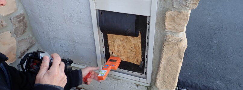
Kia America, Inc. (Kia) is recalling certain 2016-2022 Sorento, 2021-2022 Sorento Hybrid (HEV), 2022-2023 Sorento Plug-In Hybrid (PHEV), and 2017-2022 Sportage vehicles equipped with a tow hitch harness installed as original equipment, or purchased as an accessory through a Kia dealership. Debris and moisture accumulation on the tow hitch harness module printed circuit board (PCB) may cause an electrical short, which can result in a fire.
Remedy
Owners are advised to park outside and away from structures until the recall repair is complete. The remedy is currently under development. Owner notification letters are expected to be mailed November 14, 2022. Owners may contact Kia customer service at 1-800-333-4542. Kia’s number for this recall is SC249.
Notes
Owners may also contact the National Highway Traffic Safety Administration Vehicle Safety Hotline at 1-888-327-4236 (TTY 1-800-424-9153), or go to www.nhtsa.gov.