Category: Case Studies

Retail Safety Evaluation of a Watermelon Display

Basic Fact Pattern
  • Trip and fall event in a big box store, involving a watermelon display
  • Multi-million dollar claim following a similar case resulting in a previous $7.5MM verdict against the Defendant one year earlier.
  • Exact fall mechanism was unclear and video surveillance did not capture a good angle of the incident.
  • Same Plaintiff’s attorney as the previous case, but with a different safety expert.
Investigative Actions Taken
  • Deposition testimony and other available documentation was reviewed.
  • Opposing retail safety and biomechanical expert reports were reviewed.
  • Cross examination questions were developed for unqualified opposing safety expert.
  • Research study cited by opposing safety expert was fully reviewed, as well as other research by the same individual, which was not addressed by the opposing expert.
  • Safety policies and procedures were compared to national consensus-based voluntary safety standards.
  • The use of the watermelon display at the time of the incident was compared to the manufacturer’s recommendations for the use of the display, the grocery industry recommendations for the use of the display, and the merchandising use of the same display throughout 15 different retail chains.
  • A key piece of evidence in the previous case was also re-reviewed.
Determinations Made
  • The key piece of evidence in the previous case was falsely presented by the previous expert.
  • The watermelon display, as utilized at the time of the incident, was consistent with industry standards, safety standards, and merchandising in service at competing retail chains.
  • The research cited by the opposing expert did not present the conclusions alleged by the opposing expert report.
  • The alternative merchandising suggested by the opposing expert for this case would have defeated several of the safety features already built into the display, rendering the display less safe, rather than more safe.
Involved Experts: 
  • Benjamin Irwin, P.E., DFE
  • Travis Wells, P.E.

Desaturation Testing – Modified Bitumen Roofing Membrane

Desaturation Testing of Modified Bitumen Roofing Membrane

Manufacturing facility with several large buildings covered with granule surfaced modified bitumen (mod-bit) roofing membranes. Concerns were raised regarding hail-caused damage to the roofs. The mod-bit roofs varied in age and had numerous regions where granules were missing that were presented as examples of hail-caused damage. Our client needed to know if the roofs had been damaged by hail.  

Mod-bit roofing samples and their substrates were removed and tested in the HRT laboratory to determine if regions of missing granules were caused by hailstone impacts and to determine if the roofing samples had been damaged by hail. Samples were visually and tactilely examined by laboratory personnel and then samples were processed via hot solvent desaturation, which removes the bitumen and surfacing, allowing the reinforcements to be closely examined for ruptures or strains consistent with hail impact forces. 

Overview of property
Area presented as being related to a hailstone impact (left) and close-up (right)

Prior to desaturation, the samples and substrate taken from the roof were mounted to a panel and impact tested with various sizes of ice balls. Ice balls were frozen solid and propelled perpendicular to the test panel at free-fall velocities of similar sizes of hail to replicate worst-case impact conditions.

Sample and substrate mounted to test panel for hail simulation testing
Sample after impact testing with ice balls to simulate hailstone impacts

After impact testing, reinforcements were examined at the area of interest (See Figure 2) for conditions related to hailstone impact. The reinforcements were intact. Additionally, the area of interest was visually dissimilar to areas impacted by simulated hailstones.

Base ply reinforcement was intact at the area of interest after desaturation

Regions of the reinforcements subjected to simulated hailstone impacts were also examined after desaturation. It was determined that frozen solid hailstones of about 1-3/4 inches in diameter or larger could bruise the mod-bit roofing, which was a condition not detected in the field or during laboratory examination.

Base ply reinforcement at simulated hail impacts

Simulated Hail Impact Testing – PVC Roofing Membrane

Simulated Hail Impact Testing of PVC Roofing Membrane

Large school with numerous roof sections covered with a variety of single-ply roofing membrane types. One section covered with a relatively new thermoplastic polyolefin (TPO) membrane, several large sections covered with old polyisobutylene (PIB) membranes, and several sections covered with polyvinyl chloride (PVC) roofing membranes estimated at about 10 years old. School had been struck by hail on numerous occasions and the roof was examined for hail-caused damage. Some of the PVC roofing had obvious hail-caused damage and our client needed to know when the hail-caused damage had occurred.

Samples of the PVC roofing were removed and tested in the HRT laboratory to determine the minimum size of hail that could damage the PVC membranes and to determine what size hail would create similar size fractures in the membrane and similar dents in the insulation. Samples and substrate taken from the roof were mounted to a panel and impact tested with various sizes of ice balls. Ice balls were frozen solid and propelled perpendicular to the test panel at free-fall velocities of similar sizes of hail to replicate worst-case impact conditions. 

Overview of campus
Hail fracture on bottom of PVC membrane
Hail fracture on bottom of PVC membrane with backlighting

Based on simulated hail impact testing, the minimum size of hail that could cause similar impact damage to the PVC membranes was 1-1/4 inches in diameter. Based on a review of weather records, information gathered during our inspection, and laboratory test results, there was one specific storm that could have caused the fractures in the PVC membranes.

Impacts from ice balls measuring 1, 1-1/4, and 1-1/2 inches in diameter (left to right)
Simulated hail impacts used to compare dents in insulation

Hail-caused dents in the insulation were consistent in size and depth as dents resulting from simulated hailstone impacts made with ice balls measuring 1-1/4 inches in diameter, corroborating the hail-caused damage to the PVC roofing membranes were likely caused by hailstones measuring about 1-1/4 inches in diameter.   

Hail dent in insulation (left) and similar dent with 1-1/4 inch diameter ice ball (right)

Stains on Sculptures – Multi-Disciplinary Investigation

Basic Fact Pattern

  • A mysterious repetitive staining was discovered on a marble sculptural installation within a construction work zone at a major museum in Michigan.
  • The marble pieces were sculpted using water jetting technology in Spain, after which they shipped internationally on a freight barge in partially open crate containers.
  • The staining was random in nature, but tended to appear in horizontal joints, but not vertical ones.
  • The staining would re-appear over the course of more than one year, but not always in the same locations.
  • Previous experts had speculated about possible moisture entrapment within the marble pieces and/or moisture absorption into the marble during shipping in improper containers.
Overview of Sculpture
Sculpture area under construction
Investigative Sciences Employed
  • The entire sculptural installation was 3D scanned in place in color to document the locations where the staining currently existed, in combination with the joint locations throughout the installation.
  • An infrared scan of the marble surfaces was conducted to determine if patterns of moisture and/or air migration were detectable within the joints of the sculptural installation.
  • A temperature and humidity survey was taken on a grid system within the room to determine if patterns of moisture and/or air humification were detectable within the museum room.
  • Portions of the installation materials that had not yet been installed were sampled for chemical testing, including shavings from the backside of one of the marble pieces and the supporting structural framework, attachment, and lateral anchorage elements.  Shavings of discolored marble were also collected from inside of one of the stained horizontal joints.
  • Historical data regarding the appearance of staining over time from the museum were compared to the Building Management System temperature and humidity readings obtained within the construction zone over time.
Stains between horizontal joints
Back of sculpture

Determinations Made:

  • A lack of complete environmental controls within the construction zone was causing seasonal fluctuations in temperature and humidity, affecting the absorption, release, and condensation of moisture into and out of the marble pieces over time.
  • Environmental conditions present at the time of installation of each individual piece directly affected the timing of when staining would appear within any given marble piece.  Differences between the marble pieces themselves also caused many pieces to not exhibit staining at all.
  • The white marble material contained a soluble salt impurity that was released only in the presence of bulk water.
  • Staining only occurred during the moisture condensation phase of the indoor environmental changes.  Due to variations between the conditioned front side of the sculpture and the unconditioned backside of the sculpture, vapor drive expelled the excess moisture through the joints.
  • Welded stainless steel lateral anchorage plates were embedded into gouges in the stone pieces at the horizontal joints only.  Condensed bulk water collected in the gouges, releasing the salts, interacting with the anchors and/or their welds, thereby forming the colored contaminant, which was then transported through the horizontal joints by the vapor drive, depositing the colored contaminant on the surface of the sculpture.
Involved Experts: 
  • Benjamin Irwin, PE, DFE
  • Everett Lenhart, PE
  • Matt Westrich, PE
Welded stainless steel lateral anchorage plates

Fire At A Medical Building

medical-fire-damage

Haag inspected for fire, smoke, and water damage, photo-documented the loss, wrote a detailed scope and estimate for restoration, and addressed code compliance issues. The building was restored within two weeks.

When fire gutted one suite of a 5,500-square-foot medical plaza, smoke, soot, and water affected the entire two-story building. Haag Construction Consulting provided a rapid response: inspecting, diagraming, and digitally photographing the entire facility. Our investigation found contamination throughout the HVAC system; dead air spaces above ceilings also suffered severe smoke and soot fallout. Working closely first with the mitigation contractor and then with the general contractor, we established a scope and cost for the mitigation and mapped out a plan for completing the project with minimal disruption to tenants’ day-to-day operations. Within two weeks the entire medical plaza had returned to normal operation.

Accident Reconstruction – Tractor Truck v Passenger Vehicle

vehicle-damage

Haag Engineers investigated an accident involving a truck tractor and a passenger vehicle which occurred on an interstate highway.

Haag was asked to analyze a multi-vehicle accident involving a passenger vehicle and a truck tractor. Within 24 hours of the accident, Haag Forensic Engineers arrived on the scene and were able to locate and measure pertinent data including tire marks, roadway gouges, liquid debris, and guardrail damage. We were able to determine the paths of the vehicles prior to and after the collision. We investigated the vehicles to document the location and extent of damage that occurred during the accident. Based on our analysis, we were able to determine the path of the passenger car, events prior to collision with the truck, points of impact during the accident, and how this information confirmed our sequence of events. When witness reports were received, they were consistent with our analysis. 

truck-damage
road-location-of-accident

Airport Hangar Roofs Failure Assessment

airport-hanger

Haag completed a forensic evaluation of four recently constructed airplane hangar buildings which sustained metal roofing damage, as part of a subrogation investigation.

Haag engineers evaluated the design and construction of the roofs at recently constructed airplane hangar buildings.  These buildings near the coast sustained extensive damage to their metal roofs during a hurricane with wind speeds well under what the code required them to withstand. Our analysis revealed significant installation deficiencies including missing fasteners at critical edge zones and fasteners that were incorrectly anchored into the soffit instead of the eave purlins.  Analysis of the design revealed inadequate uplift resistance in two of the three wind zones.  Our research also revealed that the manufacturer had later recognized a problem with this roof system in high wind areas following the 2004 and 2005 hurricanes and developed a more robust system to address these issues, after these roofs had been constructed and failed.  Haag presented compelling evidence during mediations that led to the resolution of the subrogation phase.

airport-hanger-roof-damage

Brick Veneer Collapse

brick-veneer

Haag Engineering was asked to determine cause of exterior masonry veneer damage, and when that damage occurred.

Haag Engineers inspected an apartment building on two occasions: first to document the existing condition of the brick veneer, and second to document the method of securement of the veneer to the exterior wall as the veneer was removed from the building. The second inspection provided the basis for our opinion that there were an inadequate number of brick ties to support the veneer causing lateral deflection from the wall. We researched the local building code at the time of original construction and confirmed that the veneer was not installed per code. Veneer movement had occurred over time since the building was constructed.

brick-veneer-detail
brick-veneer-2

Collapse on The Set of Titanic

Titanic-Image

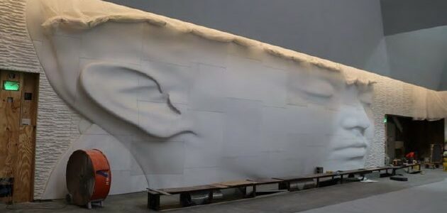
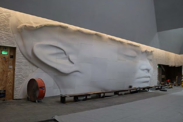
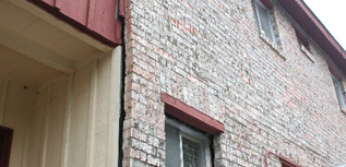
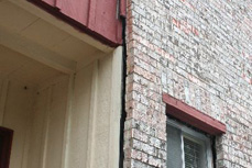
Haag Engineering Co. consultants were called to the set of the feature film Titanic to perform an inspection following collapse of part of the set.

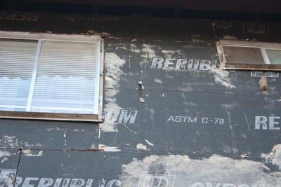
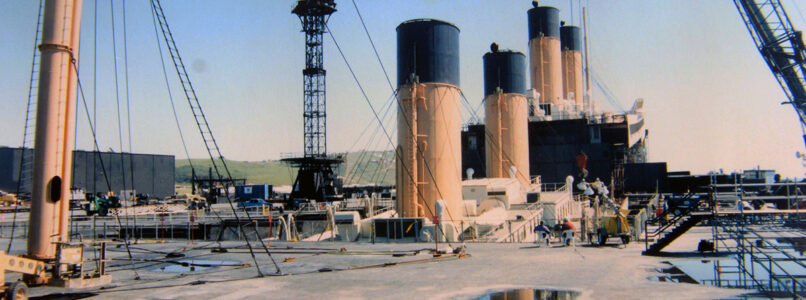
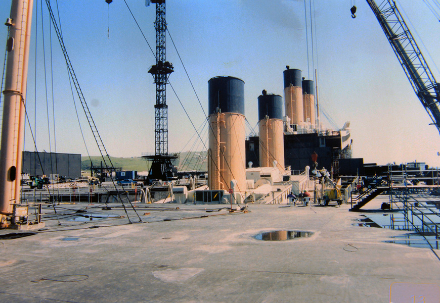
In February 1997, Haag Engineers were called to the movie set of the feature film Titanic. Ironically, the 90% scale movie set “sank” near the end of filming. The overall model was a steel frame mostly on dry land that was clad with metal panels to look like a ship. To simulate sinking, the bow was progressively tilted into a pool of water by lifting the entire frame and cutting the columns shorter. For the final scenes, the bow section was a separate set, supported by a series of hydraulically-actuated cables and buoyant foam blocks to make the set appear to float while it was being actuated with the cables. (The flotation blocks could not support the weight.) Unfortunately, a series of modifications needed to improve realism resulted in support failures that let the set sink, interrupted filming, left expensive actors and crews idle, and impacted actor confidence in the structure.

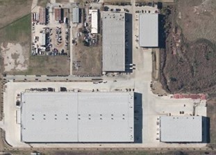
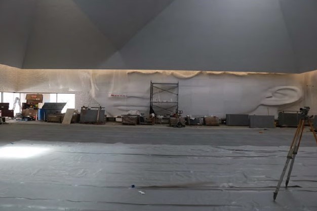
The set of Titanic was housed in a brand-new movie studio, complete with a 17 million gallon water tank (the largest ever constructed) on the coast of Rosarito, Mexico. When the film Titanic was released on December 19, 1997, it was the most expensive movie ever made, costing about $1 million per minute of screen time, exceeding $200 Million. (IMDB.com)

“The problem with the set, at the time I arrived, was that they weren’t really certain what had occurred. All they knew was that it was suspended on cables and flotation blocks at the time that it partially collapsed,” said David Teasdale, P.E., Haag Principal Engineer and VP of Engineering Services. “We had to wait a day while the tank was drained, and we took that time to learn the structure, review plans, talk to the designers and users, and tour some of the other sets where filming continued.  The set had broken and partially sank once earlier, and different groups had different concerns about why.  A film production is unique, in that, down days are factored into the film schedule.  Therefore, the business interruption claim is not confirmed until filming is complete and it is known that the accident actually cost any time.  In this case, the actors and crew were costing many thousands of dollars per day.”

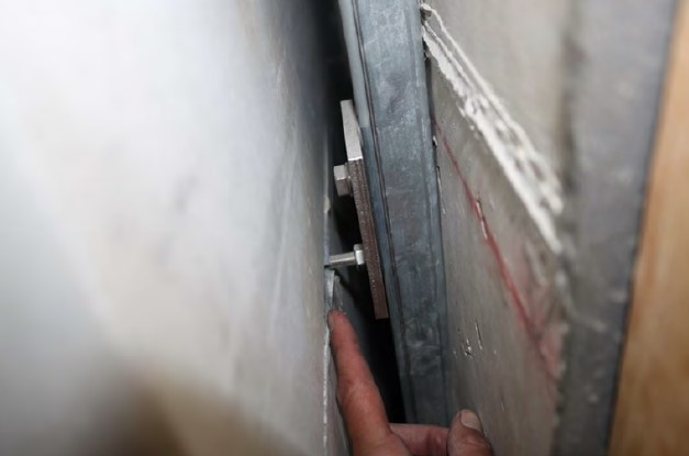
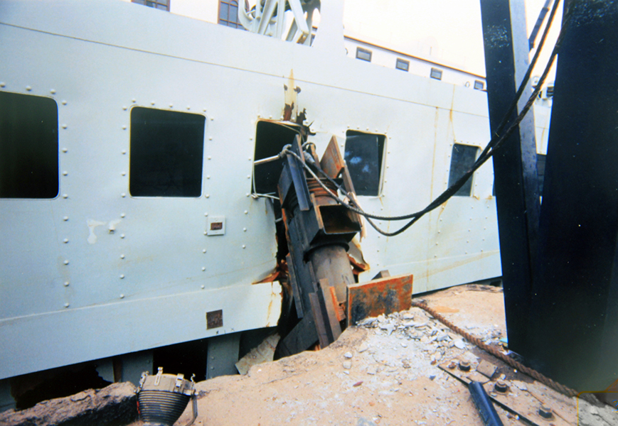
“Once the tank was drained, we observed that one support leg had broken loose, kicked out, and allowed the set of the ship to tilt into the pit of water.  In essence, more flotation blocks were called for to improve the buoyant look during filming, and there was only so much room under the set to fit them in.  When the extra blocks were added, the cross braces had to be moved higher on the columns.  The structural contractor had completed his work and left the site, so he subcontracted a local welding crew to do the work from an engineer’s plan.  One main support leg had pulled loose due to a bad weld, and the bad weld was one of many.  The solution was pretty simple. First and foremost, the repair needed to be implemented quickly, because time is money, and secondly, since it had failed once before, we needed to restore trust in the set. Therefore, Haag Engineers were included in the repair oversight.  Subsequently, we were asked to assist characterizing the failures to help others define whether they met the definitions for insured delays.  Haag also testified at the subrogation arbitration.” 

A forensic consultant needs to do more than simply identify the problem, and Haag Engineering has a long history of identifying problems large and small, helping with the solution, communicating the information needed to a variety of parties with different interests, and providing the engineering perspective needed for others to resolve any resulting disputes.

by David Teasdale, P.E., Principal Engineer & VP of Engineering Services

David Teasdale specializes in structural evaluations, earthborne and airborne vibrations, geotechnical evaluations, general civil engineering, and wind and related storm effects.  He is the primary author and presenter of a Haag classroom seminar course on earthquake damage assessment and Haag’s California Earthquake Adjuster Accreditation course.

Titanic-image-cropped
Titanic-Damage

Custom Wheel Display Accident

wheel-display

Haag Engineering was asked to determine the likely cause of an accident involving a custom wheel display, and to evaluate the displays adequacy and safety.

Haag Engineering reviewed numerous depositions, examined the involved auto parts store, monitored Plaintiff’s expert’s deposition, examined Plaintiff’s expert’s exhibit, examined custom wheels and holders similar to those used in the involved display, and tested an exemplar custom wheel display to determine the wheel’s susceptibility to external forces and displacement from the holder.

wheel-display-detail