Assessing Hail Damage:
Part 2 – Hail Inspection Protocol
By Justin Kestner, P.E., Steve Smith, P.E., and Jim Chaney, CPCU
This is the second of a two-part series on hail damage. Part 1 focused on wording choices used in reports to describe hail effects. Part two focuses on proper hail inspection protocol, damage criteria, published research, and terms used in the assessment of hail-caused damage, specifically asphalt shingles. We have already received questions from Part 1 which are addressed in Part 2 below. If you have not read Part 1 yet, please consider reading that first.
From time to time, we at Haag feel the need to clarify a few important points about hail damage, research papers pertaining to hail published by Haag and Haag’s criteria for damage. It is the latter that seems to have been misinterpreted by many in recent years with respect to asphalt shingle roofing. The last time we published a clarification with respect to hail damage to asphalt shingles was in 2006.
One of the most common questions posed to Haag engineers, in the field and in our classroom presentations, is regarding the criteria considered when assessing hail-caused damage, especially as it pertains to asphalt shingle roofs. Seemingly, people tend to get sidetracked in considering specific shingle surface features without considering the singular, most important aspect of any hail inspection: Determining “Did hail cause the condition?” Roofing consultants should be knowledgeable on the technical aspects of the roofing product they are examining, including how the product is manufactured and installed, how the product performs with regard to weathering, how to recognize manufacturing anomalies, and how to identify hail- or wind-caused damage. Amazingly, we often read hail assessment reports by other organizations that fail to establish whether there is evidence of hail hailfall at a site and whether the evidence indicates hail was capable of causing the condition(s) in question. Documenting collateral effects of hail builds a strong foundation for an assessor’s opinion(s) regarding the effects of hail on a roof.
Determining whether or not hail caused a certain condition requires sound, systematic inspection procedures, thorough documentation, knowledge of the roofing product in question, and sometimes testing. Haag has conducted numerous research projects over the decades and utilizes our laboratory to analyze hundreds of roofing samples each year in support of our engineers, construction consultants, outside clients, and even non-Haag roof consultants. Our research has helped the industry better understand the effects of hail, established the minimum size of hail able to damage different roofing types (threshold size), and even set the standard for hail damage quantification.
Haag began ice ball impact testing in 1963. Over the years, Haag has impacted numerous types of roofing, siding, other building components, cladding, automobiles, aerospace products, and others. We remain best known for our expertise of assessing hail damage to roofing. Among our research papers on hail are Hail-Fall, Roofing, and Impact Testing (Morrison et. al., 1997); Long-Term Effects of Hail Impact on Asphalt Shingles—An Interim Report (Morrison, 1999); Hail Damage Threshold Sizes for Common Roofing Materials (Marshall et. al., 2002); and Hail Damage to Asphalt Roofing Shingles (Marshal et. al., 2004). The first of these papers established that hail-caused damage to an asphalt shingle in roofing is a bruise (fracture of the reinforcing mat), puncture, or displacement of granules sufficient to expose underlying bitumen. The second of these papers found locations on shingles which were impacted by simulated hailstones in our laboratory at the initiation of the study, but did not fracture the shingle, showed no identifiable changes in granule coverage when examined after 11 years of natural weathering in north Texas. A sample of Haag’s publications can be found on Haag’s website here.
Haag pioneered the test square methodology for hail damage inspection of roofing in the 1970s. This protocol, which is based on Haag’s extensive testing and field observations, has been peer reviewed and formally published at the North American Conference on Roofing Technology. A copy of this paper can be found here. A copy has also been available on the website of the National Roofing Contractors Association (NRCA) for their members. This protocol has been widely adopted throughout the industry and has become the de facto industry standard.
Test squares are 100-square-foot areas (commonly in the form of 10-foot by 10-foot squares) within which the inspector performs up close visual and tactile inspection of roofing for hail damage. At least one test area inspection is performed per each direction of the roof (e.g., north, south, east, and west). Test squares should not be obstructed by overhanging trees (if possible) and should be representative of the general condition of the roof. Consider additional test areas if notably different roof conditions are present; for example, an older 9:12 pitched slope and a new 3:12 porch addition slope on the rear of the building. With respect to asphalt shingles, the inspector looks for hail-caused bruises, punctures, or other hail-caused conditions within 100 square-foot test areas. The number of damaged shingles per direction of roofing square is then extrapolated based on the test square results. Poorly supported shingles along valleys, ridges, and edges of the roof are evaluated separately as part of this protocol. An economical decision to repair or replace a roof can be made after the extent of hail damage is known.
As noted in the publication of Haag’s test area protocol and as recognized by many throughout the roofing industry, various causes of granule loss in asphalt shingles often are confused with hail-caused effects. Weathering, material issues, foot-caused scuffs/marring, backed-out fasteners, lichens, blisters, tree abrasions, bird droppings, and mechanical scuffs/gouges from installation, inspection, and maintenance activities can all cause conditions that may be mistaken for hail effects on asphalt shingles. When localized regions of missing granules are found in generally circular patterns on a roof subjected to hailfall, some people in the industry conclude the granules were displaced by hail without comparing the frequency or distribution of the missing granules to the frequency of hail at the site and the known, random distribution of hail, especially if the hailfall approached published threshold sizes (1 inch or greater for three-tab shingles and 1-1/4 inches or greater for laminated shingles).
Importantly, Haag’s roof assessment protocol involves comparative analysis of various surfaces at the property (including but not limited to the roof) to establish evidence of hailfall, to determine if the hailfall was recent, and to discern the approximate size, hardness, and directionality of the hail. Utility junction boxes, fences, gutters, downspouts, decks, and air-conditioner condenser fins are all good surfaces to evaluate to gain a better understanding of the characteristics of hailfall at a site, including recent and non-recent hail. From this surface analysis, an experienced inspector can determine if hail that fell recently at the site possessed the necessary properties to damage the roof, if damaging hail had fallen long ago, or if there is no evidence of damaging hailfall at all. Ideally, the surface analysis is performed first to inform the inspector of the hail history at a location. Then examination of the roof can be performed already having the knowledge of recent and past storms, allowing the inspector to develop informed opinions regarding conditions observed on the roof. Next, poorly supported shingles along ridges and valleys are assessed to determine if hail was able to damage the roof, because these shingles are the easiest for hail to bruise or puncture. This step is crucial for accurate hail damage assessment, because if hail was substantial enough to damage well-supported shingles within the field of the roof, some of these less well-supported shingles should also be damaged. Lastly, test areas are inspected to quantify the total amount of damaged shingles on the roof. By conducting hail inspections in this order, the inspector has a sense of hailfall at the site when considering roof surface anomalies within test areas.
Hail-caused damage to asphalt shingles was previously described in this blog as “a bruise (fracture of the reinforcing mat), puncture, or displacement of granules sufficient to expose underlying bitumen.” Problems with hail damage assessment to asphalt shingle roofing often arise when regions of missing granules are misidentified as being hail-caused or when the significance of missing granules is not understood.
One organization that has addressed granule loss with respect to cosmetic or functional damage is the Canadian Asphalt Roofing Manufacturers’ Association (CASMA). CASMA issues Technical Bulletins from time to time to address issues pressing to the asphalt roofing industry. CASMA issued Technical Bulletin #14 (Updated in June 2019), which addresses hail-caused damage to asphalt shingles. The bulletin describes small regions of missing granules caused by hail, as an aesthetic condition with little impact on the life of the roof. The bulletin further describes hail-caused damage in functional terms as sufficient damage to cause a leak or a reduction in service life. It clarifies functional damage as significant granule loss “easily visible from the ground, large areas of asphalt becoming exposed” or shingle fracture/penetration which can be seen as fractures through the back of the shingle.
It should be noted that the CASMA definitions of “functional” and “aesthetic” (cosmetic) do not necessarily correspond with the use of those terms in insurance policies, if those terms are indeed used. An insurance adjuster should always evaluate specific policy definitions and language when determining coverage under an insurance policy.
Haag has studied the effects of granule loss on asphalt shingles in our paper titled “Hail Damage to Asphalt Roofing Shingles. A portion of the paper is dedicated to a granule loss study. In the study, various quantities of granules were removed from the shingles, which were then left to weather in the Dallas, Texas area for 10 years. One of the shingles studied was weathered upslide down, exposing asphalt with no granule coverage. After 10 years, the only shingle that exhibited substantial weather-caused erosion was the shingle with no granule surfacing. The other shingles exhibited faded and/or oxidized asphalt where exposed, but no exposed reinforcement fibers and no surface cracks or visible erosion.
In summary, granule loss on asphalt composition shingles has many causes, including hail. Features visible in shingle surfaces should only be attributed to hail impacts if hailstones at the site were capable of causing the conditions. Comparative analysis of exposed surfaces should be made to determine the relative size, hardness, frequency, and damage-causing potential of hail that fell at a site before roofing damage determinations are made. Careful, thorough inspection and documentation procedures should be followed to support any opinions rendered. Qualified roofing consultants should be capable of discerning hail-caused conditions from weathering, manufacturing, or mechanically-caused conditions. Hail-caused damage to an asphalt shingle roof typically takes the form of displaced granules and a corresponding bruise in the shingle. If hail scuffs granules from a shingle sufficient to expose substantial coating bitumen, Haag considers that to be hail damage due to the potential loss of remaining service life. If a roof, however, was at or near the end of its useful service life at the time of the hailstorm, then other regions on shingles where asphalt was already exposed due to weathering, foot-traffic, bird droppings, etc., would result in weathered openings long before areas where granules may have been recently displaced by hail. In these instances, granules scuffed away by hail would not have any effect on the performance of the roof, unless accompanied by a bruise.

Justin Kestner is the CEO of Haag Global and the President of Haag Engineering Co., where he also serves as a Principal Engineer. He is a licensed engineer in 17 states and has inspected thousands of roofs.
Steve Smith is the Director of Haag Research & Testing Co. and a Principal Engineer at Haag Engineering. He has co-authored several papers on hail damage and has inspected thousands of roofs. He is a licensed engineer in 6 states and can be reached at ssmith@haagglobal.com.
Jim Chaney is the Director of Curriculum and Senior Instructor for Haag Education Co. He has 12 years of insurance adjusting experience and an additional 12 years as a full-time trainer. He was also a community college adjunct faculty member developing and teaching insurance claims courses for five years. Jim has an all-lines adjuster license in Texas and has been approved to teach adjuster CE in multiple states. He can be reached at jchaney@haagglobal.com.
Any opinions expressed herein are those of the author(s) and do not necessarily reflect those of Haag Engineering Co., Haag Construction Consulting, Haag Education, or parent company, Haag Global, Inc.
___________________________________________________________________________________________________________
As we celebrate Haag’s 95th anniversary in 2019, we are looking back at some of the noteworthy projects Haag Engineers and Consultants have been involved with over the last 95 years. Each month in 2019, this blog will feature one unique, important project, as selected by our senior staff. This month, we’re featuring the Titanic movie set, plus Assessing Hail Damage, Part 2: Hail Inspection Protocol.
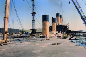
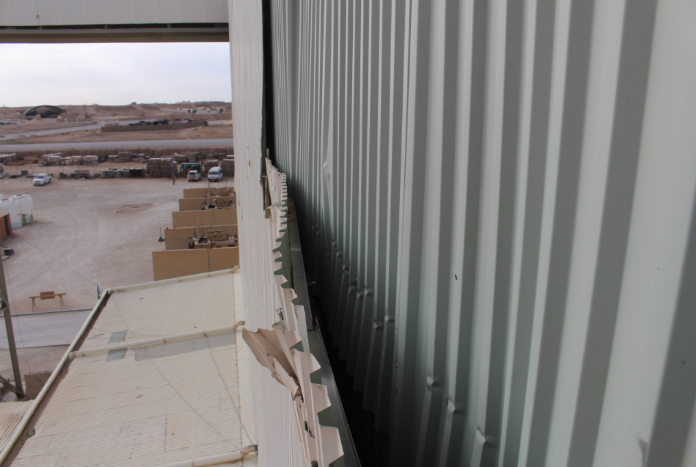
Titanic Movie Set Collapse
In February 1997, Haag Engineers were called to the movie set of the feature film Titanic. Ironically, the 90% scale movie set “sank” near the end of filming. The overall model was a steel frame mostly on dry land that was clad with metal panels to look like a ship. To simulate sinking, the bow was progressively tilted into a pool of water by lifting the entire frame and cutting the columns shorter. For the final scenes, the bow section was a separate set, supported by a series of hydraulically-actuated cables and buoyant foam blocks to make the set appear to float while it was being actuated with the cables. (The flotation blocks could not support the weight.) Unfortunately, a series of modifications needed to improve realism resulted in support failures that let the set sink, interrupted filming, left expensive actors and crews idle, and impacted actor confidence in the structure.
The set of Titanic was housed in a brand-new movie studio, complete with a 17 million gallon water tank (the largest ever constructed) on the coast of Rosarito, Mexico. When the film Titanic was released on December 19, 1997, it was the most expensive movie ever made, costing about $1 million per minute of screen time, exceeding $200 Million. (IMDB.com)
“The problem with the set, at the time I arrived, was that they weren’t really certain what had occurred. All they knew was that it was suspended on cables and flotation blocks at the time that it partially collapsed,” said David Teasdale, P.E., Haag Principal Engineer and VP of Engineering Services. “We had to wait a day while the tank was drained, and we took that time to learn the structure, review plans, talk to the designers and users, and tour some of the other sets where filming continued. The set had broken and partially sank once earlier, and different groups had different concerns about why. A film production is unique, in that, down days are factored into the film schedule. Therefore, the business interruption claim is not confirmed until filming is complete and it is known that the accident actually cost any time. In this case, the actors and crew were costing many thousands of dollars per day.”
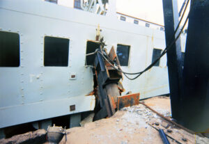
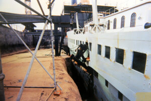
“Once the tank was drained, we observed that one support leg had broken loose, kicked out, and allowed the set of the ship to tilt into the pit of water. In essence, more flotation blocks were called for to improve the buoyant look during filming, and there was only so much room under the set to fit them in. When the extra blocks were added, the cross braces had to be moved higher on the columns. The structural contractor had completed his work and left the site, so he subcontracted a local welding crew to do the work from an engineer’s plan. One main support leg had pulled loose due to a bad weld, and the bad weld was one of many. The solution was pretty simple. First and foremost, the repair needed to be implemented quickly, because time is money, and secondly, since it had failed once before, we needed to restore trust in the set. Therefore, Haag Engineers were included in the repair oversight. Subsequently, we were asked to assist characterizing the failures to help others define whether they met the definitions for insured delays. Haag also testified at the subrogation arbitration.”
A forensic consultant needs to do more than simply identify the problem, and Haag Engineering has a long history of identifying problems large and small, helping with the solution, communicating the information needed to a variety of parties with different interests, and providing the engineering perspective needed for others to resolve any resulting disputes.

by David Teasdale, P.E., Haag Principal Engineer & VP of Engineering Services
David Teasdale specializes in structural evaluations, earthborne and airborne vibrations, geotechnical evaluations, general civil engineering, and wind and related storm effects. He is the primary author and presenter of a Haag classroom seminar course on earthquake damage assessment and Haag’s California Earthquake Adjuster Accreditation course.


 As founder of Firensics, Inc., I combine my lifelong experience and training in fire investigations with the training I received as an adjuster to create an approach to fire investigation and report product that best serves your needs through quick response time, clarity, and ease of use. As a member of a number of professional organizations, I am actively and constantly working to improve the industry of fire investigation.


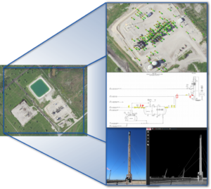
 Marcie Deffenbaugh is the Manager of GIS Services for Haag Technical Services, a division of Haag Global, Inc. In this role, Ms. Deffenbaugh oversees initiatives related to GIS planning, system design, and system administration. She also manages a staff of GIS technicians, analysts, cartographers, and project administrative assistants who provide data validation and project management services for oil and gas clients. As the primary liaison between the client management teams and Haag Technical Services personnel, Ms. Deffenbaugh provides technical consulting services on a regular basis.