Category: Articles

Fast Fires and Hot Fires, July 2020 Blog

Haag Firensics is dedicated to providing the highest-quality forensic investigations of fires and explosions in the industry. Our team of seasoned and court-tested investigators is committed to quickly finding the answers you need through industry-recognized scientific methods. With a thorough understanding of subrogation, liability, and fraud, Firensics makes your job easier by answering all of your questions for O & C investigation and providing technical reports, if requested, within 5 business days for most non-legal residential and auto assignments. The team at Firensics is led by Director of Fire Investigation Services, Ed Roberts, IAAI-CFI– a seasoned fire investigator with over 1,500 fire investigations and 25 years of experience investigating fires.


Fast Fires and Hot Fires
A couple terms that you might hear your fire investigator using, but may not understand precisely what they mean to you and your assignment, are “fast fires” and “hot fires”.
Fast Fires–
You may have heard an investigator or a witness referring to a fire as intentionally set because it was a fast fire. Is this a legitimate conclusion to make? It depends. Natural fire progression should be fairly predictable. If fire growth and spread appear to be at odds with expectations, further analysis may reveal they were “helped” along intentionally. Click the video of a demonstration and further explanation.

Hot Fires–
Another term you might hear your fire investigator using, but may not understand precisely is “hot fires.” This term has been used in the past as a justification for a fire cause being classified as incendiary. For example, “We know it was intentionally set because it was a hot fire.”
But is that true? Are incendiary fires especially hot? Is there any validity to the claim that set fires are hot fires? Click below for more information.


Edward G. Roberts, IAAI-CFI, Director of Fire Investigation Services

As founder of Firensics, I combine my lifelong experience and training in fire investigations with the training I received as an adjuster to create an approach to fire investigation and report product that best serves your needs through quick response time, clarity, and ease of use. As a member of a number of professional organizations, I am actively and constantly working to improve the industry of fire investigation.

  • IAAI-CFI, CFEI, CVFI, CFII
  • 1500+ fire and explosion origin and cause investigations
  • Court-proven and reliable, including mediation, arbitration, and depositions
  • Published internationally
  • Obtain recorded statements
  • Provide educational programs to insurance and investigation communities

Any opinions expressed herein are those of the author(s) and do not necessarily reflect those of Haag Engineering Co., Haag Construction Consulting, Haag Education, or parent company, Haag Global, Inc.

Impact Resistant Shingles, June 2020 Blog

Impact Resistant Shingles

In May 2019, Haag Research & Testing Co. (HRT) published the blog for the Haag Global newsletter which discussed the history of simulated hail testing performed by Haag over the years. We also explained our current ice ball launching platform (the IBL-7) and mentioned two impact testing protocols used to classify the impact-resistance of roofing products. (The blog can be viewed here.)

Since then, HRT conducted a research project to put several impact-resistant roofing products to the test. Five asphalt shingle designs from four different manufacturers were tested against their published impact ratings to determine if they would perform as advertised. Although two of the five shingles performed consistent with their ratings, the study revealed an important shortcoming in the impact testing standards. Test standards UL 2218 (steel ball drop test) and ANSI/FM 4473 (propelled ice ball test) specify visual examination of the tested roofing products after testing to determine if the products were compromised by the impacts. These test standards do not currently evaluate the reinforcements within asphalt shingles or other bituminous roofing types. Consequently, reinforcements can be fractured or strained during impact testing, yet go unnoticed by laboratory personnel performing the tests.

HRT not only tested the impact-resistant shingles according to both testing protocols, but also extracted the shingle reinforcements using hot solvent, a process called “desaturation testing”, after the impact testing was completed. The desaturation process not only revealed impact-caused fractures in all five of the tested shingle designs at their published class ratings, but also found fractures in their reinforcements from impacts at lower class ratings, including Class 1, which is the lowest rating. Class 1 tests involve steel balls or ice balls that impact test specimens at energies similar to the free-fall energy of hailstones measuring 1-1/4 inches in diameter. It is important to understand, the kinetic energy of a hailstone increases exponentially with size. The table below summarizes the kinetic energy of free-falling hailstones and includes the kinetic energies of Classes 1, 2, 3, and 4 outlined in UL 2218 and ANSI/FM 4473 test standards.

Four of the five shingle designs had an additional reinforcement layer, strategically placed on the back sides of the shingles which should increase the tensile strength of the shingles. The reinforcement backing, however, obstructed the view of fractures in many cases during the study, causing the visual examinations described in the tests to fall short of ascertaining the true performance of the shingles.

Desaturation testing is described in ASTM D3746 (Standard Test Method for Impact Resistance of Bituminous Roofing Systems), which is a long-standing test procedure for determining the impact resistance of asphalt built-up roofing (ABUR).  HRT performs desaturation testing during forensic examinations of roofing involved in insurance claims or legal disputes and has done so for decades. HRT is accredited by the International Accreditation Service (IAS) to perform desaturation testing and both UL 2218 and ANSI/FM 4473 impact testing protocols. HRT has the capability to propel ice balls ranging from 1/2 inch up to 4 inches in diameter, providing useful information outside the range of the ANSI/FM 4473 ice ball testing protocol. Impact testing with simulated hailstones and utilization of desaturation procedures are often performed together to gain an accurate understanding of the impact resistance of roofing products, surface conditions caused by hail, and whether or not bituminous roofing samples taken from roofs for forensic evaluations have sustained hail-caused fractures or strains in their reinforcements. Bituminous products suitable for this type of testing include asphalt shingles, ABUR, modified bitumen membrane roofing, and coal tar built-up roofing.

 The study of impact-resistant shingles performed by HRT has been peer-reviewed, and was published in the May 2020 edition of Interface Magazine (Source: https://iibec.org/). The article can also be viewed here.

Read Haag’s White Paper: Impact Testing of Impact Resistant Shingles here. 


 Steve R. Smith, P.E., Director of Research & Testing and Principal Engineer


Steve R. Smith, P.E., completed nuclear power training with the United States Navy in 1994. He was honorably discharged in 1998 and went to work for Haag Engineering Co. as Senior Laboratory Technician. Steve has performed hundreds of hail impact tests on a variety of products including roofing, siding, and automobiles.  He graduated from the University of Texas at Arlington in 2005 with a Bachelor’s degree in Mechanical Engineering and is a member of the American Society of Mechanical Engineers, the Society of Automotive Engineers, and the National Association of Fire Investigators. Steve has inspected and assessed damage to a number of roof systems, including single-ply systems, composition shingles, cedar shake and shingles, concrete tiles, slates, and built-up roofing. As Director of Research & Testing, Mr. Smith oversees all testing projects, protocols and manages Haag’s accreditation. Mr. Smith is based at Haag’s national headquarters in Flower Mound, TX.


Any opinions expressed herein are those of the author(s) and do not necessarily reflect those of Haag Engineering Co., Haag Construction Consulting, Haag Education, or parent company, Haag Global, Inc.

SPONTANEOUS GLASS BREAKAGE, May 2020 Blog

SPONTANEOUS GLASS BREAKAGE

by Brandon D. Bealmear, P.E., FMPC (Fenestration Master)

Glass breakage can be caused by a multitude of sources and most commonly from external forces. Glass can also break with an internal force generally termed as spontaneous breakage, which  refers  to  the  spontaneity  of  the  breakage  without  prior  warning or external forces. Although considered rare by most glass manufacturers, this form of breakage has personally been observed in at least five known cases in the past seven years. It has also been a misnomer that top glass manufacturers do not have issues with spontaneous breakage, but rather some of the aforementioned observed cases occurred with manufacturers deemed as top in the industry.

Definition

Tempered glass may break spontaneously without warning due to expansion of inclusion stones present within the float glass. Inclusion stones within the glass are formed from undissolved impurities from batch materials or furnace fuel. The most critical of these inclusion stones is nickel sulfide, which are formed when nickel contamination (often from stainless steel materials) combines with sulfur (sulfur dioxide is commonly used in glass production). The breakage specifically occurs when the inclusion expands greater than the glass surrounding the stone when subjected to increased temperature, such as from sunlight; hence the spontaneous breakage with no perceived trigger.

What to consider?

Glass breakage will emanate from the origination, so follow the fracture lines to the point source. The point source often times will be along an edge which is usually an indicator of external forces, but if the point source is found to be within the field of the glass it could be an instance of spontaneous breakage. External impact damage will typically cause chipping or punctures at the point source while spontaneous breakage will have an absence of such damage.

Figure 1 – Showing hexagon-shaped fragments.

Prevention

At this time, besides limiting the use of tempered glass, the only known method used to mitigate the risk of spontaneous breakage is to heat soak each piece of tempered glass. By heat soaking1, the glass is placed in an oven and subjected to increased temperatures that can expand the nickel sulfide stones. If an inclusion is present the glass will break.  Heat soaking is conducted prior to being glazed on a building and therefore not a viable option after the glass is installed. Due to the additional upfront cost, heat soaking is not a common practice.

What to look for?

The point source for spontaneous breakage most often contains two hexagon-shaped glass fragments abutted to one another. This will stand out because the remaining fragments are generally smaller and typically only have three or four sides. The inclusion can be found within the shared fracture plane between each hexagon-shaped fragment. Often times, the inclusion can be seen with optical zoom on a digital camera.

Figure 2 – Showing inclusion stone with 10x optical zoom.

Conclusion

Spontaneous glass breakage is generally distinguishable by a break pattern of two side by side hexagon fragments.

1. Heat Soak Testing, Tech Talk (2003). Viracon Architectural Glass. URL: http://viracon.com. 


Haag Engineer Brandon D. Bealmear, P.E., is an AAMA Certified Fenestration Master. Mr. Bealmear has 14 years’ experience with glass, wood, aluminum, concrete, masonry, and other construction materials. He has designed, consulted, and written quality control and forensic testing protocols for building envelopes, including fenestration systems and wall systems. His design experience includes performance consulting, mock-up evaluation and testing, construction quality control and defect evaluation, and special controlled inspections. Mr. Bealmear has also provided forensic analysis for residential and commercial properties. His experience includes material failure to structural collapse, construction defects, damage assessments from hail, wind (including tornadoes and hurricanes), earthquake, snow loading, and moisture intrusion.

Any opinions expressed herein are those of the author(s) and do not necessarily reflect those of Haag Engineering Co., Haag Construction Consulting, Haag Education, or parent company, Haag Global, Inc.

How GIS Can Help the Insurance Industry When Severe Weather Occurs, April 2020 Blog

How GIS Can Help the Insurance Industry When Severe Weather Occurs

by Marcie Deffenbaugh, Haag Technical Services

On the evening of October 20, 2019, thunderstorms erupted across the Dallas/Fort Worth Metroplex that produced strong winds, hail, and tornadoes. According to the National Oceanic and Atmospheric Administration (NOAA), a total of 10 tornadoes were identified by National Weather Service (NWS) Survey teams, the strongest of which was an EF-3 that stretched almost 16 miles across the northern portions of Dallas County. Following on the heels of that tornado, an EF-2 tracked about 2.5 miles through Garland in Dallas County. The remaining count of tornadoes included 4 EF-1s and 4 EF-0s.

Miraculously, no one was killed by the storms, but the devastation was widespread. The total estimated cost of insured damage for all the tornadoes alone is over $2 billion, which the Insurance Council of Texas claims is the costliest tornado event in the state’s history.

When sever weather occurs, insurance companies must be able to react quickly in order to assess the damage and process claims as efficiently as possible. Additionally, companies such as Haag that are often called upon to assist with damage assessment need reliable access to relational location information– where are the properties making claims; is the damage in an area consistent with the reported storm information; what was the condition of the property prior to the storm; what is the historic data for previous claims made; etc. In these scenarios, a Geographic Information System (GIS) can be a powerful tool for assessing damage that has occurred. GIS is also useful for helping insurance professionals understand and manage risk before, during, and after an event.

In the case of the tornadoes that struck the DFW area, insurance companies could have utilized GIS in the following ways to not only react to the storms, but also put plans in place to proactively prepare for future storms:

  • Based on the tornado paths and estimated damage buffers related to each tornado, identify on a map the insurance company’s policies in place that fall within affected areas.
  • Add layers to the map to help rank properties from low to high insurance values. Layers could include proprietary information such as property owner data as well as more publicly available information such as flood zones or even census data to highlight more populous areas.
  • As analysts visualize aggregated policyholder data and areas of high total-insured value, they see which locations have the most potential for significant losses.
  • For engineering firms working to assess the extent and causes of the damage, overlay historic imagery with post-storm imagery to help understand before and after conditions.

Haag’s use of GIS for the Dallas storms included Haag’s Technical Services division (HTS) quickly putting together a web map on the Haag Geoportal which showed the EF-3 tornado’s track, estimated damage buffer, and Dallas Independent School District (DISD) schools within the track and buffer area. This map included three schools with extensive damage which Haag Construction Consulting and Haag Engineering eventually assessed the extent of damage and scope and cost to repair from the storm. HTS also linked panoramic photography captured with Matterport technology to the three schools of interest which allowed users to view internal damage from their desktop or mobile devices – no trips to the field required. Further, HTS incorporated post-tornado aerial imagery from UAS (drones).

While not conclusive alone, the above steps are a great start to utilizing geospatial information to assist insurance companies and other key stakeholders with proactively preparing for storm events as well as efficiently reacting to weather disasters when they occur. We can’t stop severe weather from happening, but we can use GIS to help make proactive planning and recovery much easier.

For more information on how Haag can assist you with GIS and/or Matterport technology, please contact Marcie Deffenbaugh (mdeffenbaugh@haagglobal.com) or Kevin Kianka, P.E. (kkianka@haagglobal.com)


Marcie Deffenbaugh is the Manager of GIS Services for Haag Technical Services, a division of Haag Global, Inc.  In this role, Ms. Deffenbaugh oversees initiatives related to GIS planning, system design, and system administration. She also manages a staff of GIS technicians, analysts, cartographers, and project administrative assistants who provide data validation and project management services for oil and gas clients. As the primary liaison between the client management teams and Haag Technical Services personnel, Ms. Deffenbaugh provides technical consulting services on a regular basis.


Any opinions expressed herein are those of the author(s) and do not necessarily reflect those of Haag Technical Services, Haag Engineering Co., Haag Education, or parent company, Haag Global, Inc.

Testing Application Standard (TAS) No. 106 – Its Importance and Intended Use – March 2020 Blog

Testing Application Standard (TAS) No. 106 – Its Importance and Intended Use

In this month’s blog post, we at Haag Engineering Co. (Haag) talk about the TAS 106 (Standard procedure for field verification of bonding of mortar or adhesive set tile systems and mechanically attached rigid, discontinuous roof systems).  Within the forensic engineering, roofing, and insurance industries, we are experiencing continued use of the Florida Building Code’s (FBC) TAS 106 for the determination of wind-related damage to tile roof systems. The objective of this blog post is to simplify, understand, and ultimately convey the importance and intended uses of the TAS 106.

(Click here for the PDF version of this blog post.)

What is TAS 106? How is it used? What is it used for?

In short, and per the FBC, “This Application Standard is a product application quality control test to confirm: 1) sufficient bonding by the mortar or adhesive to the tile and underlayment in a mortar or adhesive set tile system; or 2) effective mechanical attachment of components within a rigid discontinuous roof system.”

The TAS 106 is performed to confirm if the method of attachment is sufficient/effective to resist the designed wind loads of the tile roof system shortly after the completion of a roof installation in High-Velocity Hurricane Zones (HVHZ). Per the FBC Section 1512, “…upon completion of all adhesive and mortar-set tile systems, and prior to the final inspection, field verification, and static uplift test, in compliance with TAS 106 shall be required to confirm tile adhesion to the underlayment.” Further, the FBC states, “This test may be required by the building official for mechanically attached tile systems.” Although the TAS 106 can be performed on any tile roof system, field testing in accordance with the TAS 106 is only required within High-Velocity Hurricane Zones in Florida – which encompasses only Miami-Dade and Broward Counties.

Field verification, testing, and recorded data in accordance with the TAS 106 shall be performed by a Dade County Approved Testing Agency and consists in part of the following:

The inspector must test 10% of field tiles and 20% of perimeter/corner tiles for proper attachment.  At least 97% of the tested tiles must be adequately attached; if not, the roof fails the test and requires remediation. Proper attachment shall be determined by a tile that remains bonded, does not break/crack, and/or does not lift more than 2 inches along the nose, when lifted with a static load of at least 35 lbs. or not less than 80% of the design load.

Can the TAS 106 be used to evaluate if a tile roof system is wind damaged?

No.  Rather, the TAS 106 is a product application quality control test performed by a Dade County Approved Testing Agency to confirm the adequate attachment of tile roof systems within the HVHZ. The determination of whether a tile roof is damaged by wind forces is performed through forensic inspection methodologies that do not require the use of TAS 106.  Wind damage to tile roofs typically consists of displaced or missing tiles, initiating at roof edges, corners, and peaks (susceptible areas of the roof structure exposed to higher wind uplift forces). Tile roofs also may experience indirect wind damage in the form of impacts from windborne debris or impacts from falling trees and other items that tend to accompany high-speed winds. Other factors that can contribute to the failure of tile roofs may include age, maintenance, method of attachment, and pitch of the roof slopes. (For more information and certified courses on tile roofs, as well as other roof systems, refer to Haag Education [www.haageducation.com].)

Are “loose” or “unbonded or not-bonded” tiles caused by wind?

Let’s discuss two common misconceptions related to the TAS 106 frequently encountered during roofing inspections; 1) lift at the butt-ends of mechanically fastened field tiles, and 2) unbonded or not-bonded mortar/adhesive set tiles that remain in place.

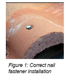
When mechanically fastened tiles are said to be “loose” or exhibit lift of 2 inches or more at the butt-end (tile nose), inspectors often attribute these conditions to wind uplift forces.  By the nature of the installation, mechanically attached field tiles can be lifted by hand to some degree, and this is reflected within TAS 106 by the allowable threshold of 2 inches.  These tiles are intended to be hung from fasteners, and correct fastener installation entails driving fastener heads nearly flush while providing an adequate gap between the head and the tile surface for thermal movement and to prevent breakage.

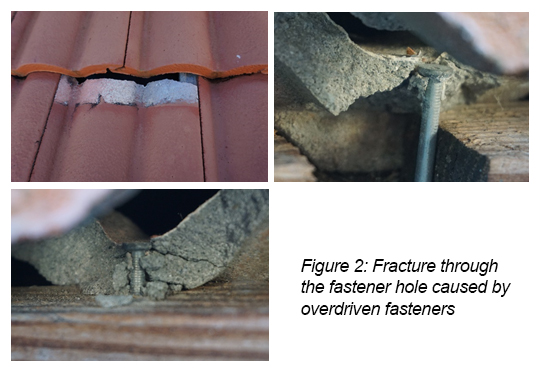
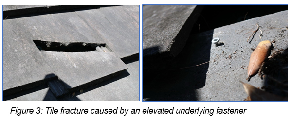
When fasteners are driven tightly against tile surfaces, tiles are prone to fracture during the attachment or as a result of inadequate space for thermal movement. Fasteners can also be under-driven, resulting in an elevated fastener. Depending on the extent of an under-driven fastener, this condition may result in a point load fracture, typically induced by foot traffic.

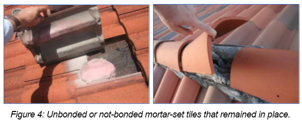
Unbonded (or not-bonded) mortar-set tiles that remain in place are commonplace and are not the result of wind forces. A bonded roof tile that is broken loose by wind uplift will not remain in place and/or be undisturbed; rather, wind forces great enough to break a bonded tile will also displace or remove the tile from the roof.  Tiles that unbonded or never bond to the underlying substrate and remain in place can be caused by a number of factors, including the following: thermal stresses; installation conditions; and/or maintenance activities. Unbonded mortar-set tiles must be periodically reset with new mortar to keep them secure.

Conclusion

Haag has identified the misapplication of the TAS 106 by roof inspectors in the determination of wind-related damage to tile roofing systems. It is Haag’s opinion that this Application Standard is not intended to be used, nor is valid on its own merit, in the determination of whether roof tiles have sustained damage from wind. Per the FBC, TAS 106 is a product application control test performed by a Dade County Approved Testing Agency to confirm adequate tile attachment of tile roof systems within the High-Velocity Hurricane Zones at the time of installation. Frequent use of TAS 106 by inspectors to illustrate unbonded (or not bonded) mortar/adhesive-set tiles, as well as an in-situ lift in excess of 2 inches at the butt-ends of mechanically attached tiles, fails to consider the installation quality of tile roofs, the effects of wind on a structure, and numerous other factors that can contribute to failure of tile roofs. Using the TAS 106 does not give any insight as to whether the roofing system was damaged by wind forces or not. We encourage the reference of this blog within the roofing industry to simplify, understand, and convey the use and importance of TAS 106.


Authors:

Aaron Duba, P.E., is a Forensic Engineer in Tampa, Florida.

John Ellis, P.E., is a Forensic Engineer in Tallahassee, Florida. 


Any opinions expressed herein are those of the author(s) and do not necessarily reflect those of Haag Engineering Co., Haag Construction Consulting, Haag Education, or parent company, Haag Global, Inc.

Understanding Earthquake Risk, February 2020 Blog

Understanding Earthquake Risk


by David Teasdale, P.E.

Earthquakes, explosions, and other ground vibrations often generate interest in the engineering and insurance worlds because they offer a chance to see structures behave differently.  Further, since understanding the response of a structure to vibrations requires more math and specialization, it can have a little more aura of mystery; however, it does not have to be that way.

Building codes are based primarily on statistical risk of a damaging event, and in the United States, we subscribe to an elastic strain energy theory for earthquake risk assessment.  (Yes, there is more than one theory for the predominant cause of earthquakes in an area.)  In the elastic strain concept, the rock volumes on either side of a fault rub against each other and bind until the strain becomes large enough to cause slip.  The sudden slip and jump in movement produces the vibrational wave that propagates out from the fault.  (Earthquakes are described with a focus, or point of origin, but the vibrational wave actually emanates out from a line corresponding to the length of the moving fault.) This earthquake mechanism lends itself well to measurement, study, and correlations between past earthquakes and predictions for the future.


The risk of damage, however, is based on much more, including the type of building, distance from the ruptured fault, depth of the ruptured fault, magnitude, duration of shaking, and to some extent the frequency of vibration.  Virtually all of these factors are unknown in advance except the building, and therefore, it is possible to overthink the important points.  Engineers and codes deal with these unknowns by adopting a number of broad-brush concepts beginning with an idealized, minimum earthquake and design parameters that are meant to save lives not prevent damage.  The state of the art for earthquake design is basically that, if conventional approaches are followed, the building performance in the next earthquake should be satisfactory with respect to life safety.  It may be disappointing to learn that codes handle the risk of a powerful infrequent earthquake much the same as frequent small earthquakes (think New Madrid in the Midwest or Oklahoma in the Plains states).  The design force levels are simply reduced, which is fine for a 500-year recurrence interval unless you’re living in the statistical 499th year.

For the forensic engineer and insurance adjuster assessing damage, it is not necessary to know the earthquake magnitude, its frequency content, recurrence interval, or virtually anything else about the quake.  It is more relevant to understand how the structure responds to a shaking event, be able to identify features that move most or stay stationary, and how the cladding materials behave when skewed.  Since the actual force levels and stresses at points within a structure are not known precisely (even when a ground motion is digitally applied to a structural computer model), field evaluation follows a comparative analysis between features that are weak/strong, stiff/flexible, anchored/unanchored, high/low, and etc.  The foundation of a building is accelerated, and as its motion changes direction, the structure above the foundation experiences amplified motion and deformation.  Understanding the behavior of a structure when shaken allows an inspector to make the necessary comparative analysis and separate out conditions that are more likely the result of other causes.

The Consortium of University Research in Earthquake Engineering (CUREE) has published a great source of information in handbook form that can be found online at https://curee.org/projects/EDA/docs/CUREE-EDA02-2-public.pdf. The California Earthquake Authority (CEA) requires certification training for adjusters that includes instruction on earthquake damage assessment, and many instructors will reference this book.  Haag Education offers a short course online and more in-depth courses for contract training that lead to CEA certification


by David Teasdale, P.E., Haag Principal Engineer & VP of Engineering Services

David Teasdale specializes in structural evaluations, earthborne and airborne vibrations, geotechnical evaluations, general civil engineering, and wind and related storm effects.  He is the primary author and presenter of a Haag classroom seminar course on earthquake damage assessment and Haag’s California Earthquake Adjuster Accreditation course. See his profile here.

Any opinions expressed herein are those of the author(s) and do not necessarily reflect those of Haag Engineering Co., Haag Construction Consulting, Haag Education, or parent company, Haag Global, Inc.

Haag’s Fire Origin and Cause Experts, January 2020 Blog

Haag’s Fire Origin and Cause Experts


In November 2019, Haag welcomed its new Fire Origin and Cause Group—Firensics. Firensics provides fire origin and cause investigations, HAZMAT investigations, evidence collection and storage, burn testing, code and research analysis, and expert witness testimony.

Firensics’ investigation services perfectly complement the fire services Haag engineers have provided for decades–fire origin and cause inspections related to mechanical failures needing a Professional Engineer’s seal.

Firensics is dedicated to providing the highest-quality forensic investigations of fires and explosions in the industry. Their team of seasoned and court-tested investigators is committed to quickly finding the answers you need through industry-recognized scientific methods. With a thorough understanding of subrogation, liability, and fraud, Firensics makes your job easier by answering all of your questions for O & C investigation and providing technical reports, if requested, within 5 business days for most non-legal residential and auto assignments.

The team at Firensics is led by Director of Fire Investigation Services, Ed Roberts, IAAI-CFI. Ed is a seasoned fire investigator, with over 1,500 fire investigations and 25 years of experience investigating fires. (See Teams profiles below)

For more information on Fire O&C, or to submit your assignment. 

FIRENSICS SERVICES—
  • ORIGIN AND CAUSE INVESTIGATIONS
    • From complex commercial fires and explosions to vehicle and heavy machinery fires to wildland fires, Firensics investigators can handle any scale or scope of investigation you bring. With a coverage area of multiple states, and a number of highly qualified and experienced investigators to support one another in large-scale incidents, we are there for you. And in the event one of our investigators disagrees with a local law enforcement investigator’s findings, we can provide an objective, second opinion at no charge.
  • HAZMAT INVESTIGATIONS
    • To some extent, every fire scene is a hazardous environment. In addition to investigators certified to manage and investigate HAZMAT sites, each of our investigators is trained to evaluate safety concerns at EVERY SCENE before beginning their investigation. This helps ensure that the professional you hire for your investigation is conscientious and safe. The last thing you need is the complication of worrying about the safety of outside contractors.
  • EVIDENCE COLLECTION AND STORAGE
    • Knowing when and how to collect evidence is only the beginning of the battle. Is your fire investigator documenting and storing evidence in compliance with standards such as ASTM E1459 and E1492? Our on-site storage facility and system are laid out to ensure your evidence is properly documented and available when the time comes.
  • BURN TESTING
    • It is one thing to claim what goes on in a fire… it’s quite another to know it. Whether it involves testing hypotheses of other experts, or the regular testing we do to enhance our training and familiarity with materials, Firensics is here to put the physical into forensic evidence.
  • CODE RESEARCH AND ANALYSIS
    • The complexity of a fire investigation can rise quickly when one is dealing with code issues. It is often simple matters that lead to big complications. At times, the origin and cause of an incident may not be as important as are involved code requirements. Furthermore, an expert referencing the wrong code may take you down a dead-end road in your subrogation case. Our investigators are trained to consider code issues concurrently with their investigation and to apprise you of any code issues that may affect litigation or underwriting concerns.
  • EXPERT WITNESS TESTIMONY
    • Firensics experts are vetted for their ability to present their findings, and our reports are designed to show that. Due to our extensive experience in the industry, every process in our company is designed to support your claims process. We follow methods consistent with industry standards and we charge the same hourly rate no matter if we are on the scene or in the courtroom.
Edward G. Roberts, IAAI-CFI, Director of Fire Investigation Services


As founder of Firensics, Inc., I combine my lifelong experience and training in fire investigations with the training I received as an adjuster to create an approach to fire investigation and report product that best serves your needs through quick response time, clarity, and ease of use. As a member of a number of professional organizations, I am actively and constantly working to improve the industry of fire investigation.

  • IAAI-CFI, CFEI, CVFI, CFII
  • 1500+ fire and explosion origin and cause investigations
  • Court-proven and reliable, including mediation, arbitration, and depositions
  • Published internationally
  • Obtain recorded statements
  • Provide educational programs to insurance and investigation communities
  • Founder and President of Firensics, Inc.

Any opinions expressed herein are those of the author(s) and do not necessarily reflect those of Haag Engineering, Haag Education, or parent company, Haag Global, Inc.

Grain Explosion Evaluation: Coshocton Grain Company, December 2019 Blog

As we celebrate Haag’s 95th anniversary in 2019, we are looking back at some of the noteworthy and important projects Haag Engineers and Consultants have been involved with over the last 95 years. Each month in 2019, this blog will feature one unique, important project, as selected by our senior staff. 

Grain Explosion Evaluation: Coshocton Grain Company

By John Z. Wlascinski, P.E., Principal Engineer

On August 13, 2014, a large grain dust explosion occurred at the Coshocton Grain Company facility in Coshocton, Ohio. The explosion severely damaged three connected silos and injured six workers. Employees were loading rail cars when the explosion happened around 4 pm, and sections of the bins toppled onto the rail cars.(1)

The 60-year-old Coshocton Grain facility was a 2.5-million-bushel capacity grain receiving, drying, and storage facility that included three slip-formed concrete storage houses standing more than 100 feet above grade at the bin deck. A single gallery spanned across all three houses; two of the houses had head houses. A tunnel network connected all three grain houses in the basement, and one of the houses to a truck dump building and to several silos across railroad tracks to the south. South of the railroad tracks were five additional concrete silos, four steel storage bins, and several small buildings.

Seven bucket elevators, 12 drag conveyors, 11 belt conveyors, two screw augers, and one tripper directed the flow of grain throughout the facility. In general, the equipment in the basement and ground-level directed flow of grain away from the dumps and bins, and to the boots of the elevators. Elevated equipment directed flow away from the elevator legs to the various silos, bins, dryers, and load out areas of the facility. There were also three dust collectors, a dryer, a truck scale, and a continuous flow scale.

Haag Engineers responded to determine the origin and cause of the explosion, which included coordinating with OSHA representatives and salvage efforts.

The explosion caused a large area of the middle house to blowout and the head house to fall to the ground and damage several railcars and railroad tracks. Haag’s original scope expanded to include documentation of the explosion site using 360° photography and scanning (3D laser scanning), evaluation of structural and mechanical damage caused by the explosion, and a cost estimate of the explosion-related damage. Collectively, this project began as an explosion origin and cause determination and expanded to include four different Haag services and seven Haag personnel.


John Z. Wlascinski, PE, CFEI, CVFI, is the Board Chairman, Houston Engineering Branch Manager, and Forensic Engineer with Haag Engineering Co. Mr. Wlascinski has been an integral part of the engineering team in Houston since 1993. He specializes specializing in mechanical failures of industrial and commercial machinery, fire suppression systems and components, piping systems and components, and oil field equipment. He has also specialized in HVAC system evaluation, fire/explosion origin and cause determination, and vehicle accident reconstruction. Prior to joining Haag, Mr. Wlascinski owned and operated two successful businesses: an automotive and heavy equipment repair company, and an underground utilities service company. Mr. Wlascinski is a licensed P.E. in 29 states, plus Washington D.C. and Puerto Rico. Mr. Wlascinski is an NAFI Certified Fire and Explosion Investigator, NAFI Certified Vehicle Fire Investigator, and a Certified Infrared Thermographer Level I. He earned his Mechanical Engineering degree from The University of Texas at Austin.

Any opinions expressed herein are those of the author(s) and do not necessarily reflect those of Haag Engineering Co., Haag Construction Consulting, Haag Education, or parent company, Haag Global, Inc.

The Texas A&M Bonfire Collapse, November 2019 Blog

As we celebrate Haag’s 95th anniversary in 2019, we are looking back at some of the noteworthy and important projects Haag Engineers and Consultants have been involved with over the last 95 years. Each month in 2019, this blog will feature one unique, important project, as selected by our senior staff. 

At approximately 2:42 am on November 18, 1999, the annual Aggie Bonfire at Texas A&M University in College Station, Texas, collapsed during construction, killing 12 people and injuring 27 others. Per Aggie tradition, the 59-foot-tall bonfire would have been lit on November 25th, the night before Texas A&M played football against the University of Texas.

The Texas A&M Bonfire Collapse

By Jim D. Wiethorn, Ph.D., P.E., Principal Engineer

I became involved with the Aggie Bonfire Collapse through a client, Leo Linbeck, Jr., who was the Chairman of the Special Commission on the 1999 Aggie Bonfire.  I developed a relationship with Mr. Linbeck after working with him on my first crane accident with Haag in 1987, and several other projects over the years.

Mr. Linbeck called and asked if I would be interested in interviewing to perform work on the collapse, which, of course, I accepted. I attended the interview with representatives of Texas A&M, McKinsey & Company (a global management and consulting firm), and various members of the commission. After much discussion, Mr. Linbeck asked if Haag would work with McKinsey as part of the peer-review committee, tasked with reviewing work as it progressed and writing an opinion letter on the practices and procedures of the five consulting firms investigating the collapse.

The Peer Review Committee’s job was to validate the engineering approach and analytical methodology used by the engineering teams investigating the bonfire collapse. The Committee consisted of Dr. German Gurfinkel, University of Illinois, structural engineer; John W. Fowler, Fowler Engineering & Construction (designed and built Chesapeake Bay Bridge-Tunnel); Dr. Monte Phillips, University of Minnesota, geotechnical engineer; and Jim Wiethorn, Haag Engineering Co., forensic structural engineer. I was appointed Chair of the committee, and I included John Stewart, P.E., and David Teasdale, P.E., to assist in this endeavor, particularly since Haag was located in fairly close proximity to College Station while the other members were out of state.

We spent approximately four months on-site gathering information, reviewing engineering techniques, and evaluating and critiquing presentation of finding by the five teams and ultimately writing a summation of our opinion.  The report was issued in April 2000 and was included in the final production of the “Texas A&M Bonfire Collapse Report”.

About a week later, a representative from McKinsey called and stated that they had decided that each commissioner would read a summation of each portion of the report. I assisted McKinsey late into the evening summarizing the results from each of the team. The following morning, the report findings were publicly presented by the commissioners at the Reed Arena.

Understanding the historical development and progression of the bonfire was extremely interesting and relevant as to how and why the bonfire’s shape changed. One interesting change was from the standard straight pine logs to gnarly oak logs. Three logs were always tied together with conventional tie-wire, so the method of wire installation was actively analyzed. It was found that freshmen would do the wiring and generally just twist the end until it broke. Inserting the logs resulted in high hoop stresses that ultimately compromised the entire structure. This change materialized due to the belief of the corps that if the bonfire collapsed before midnight, they would lose the game to Texas. Therefore, the decision was made to go from pine logs to oak logs so the fire would burn longer and maintain the vertical shape longer.

Height turned out to be another interesting aspect. Between 1910 and the 1950s, the tallest bonfire was 47 feet and all bonfires were in a teepee shape. Beginning in the late 80’s and really progressing in 1990’s the “wedding cake” designed unfolded. With the advent of the oak logs, large openings resulted. The practice of turning the logs upside down and inserting into the openings/gaps below became prevalent around 1993.

Interestingly, in 1994 the bonfire partially collapsed. When overlaid with the 1999 collapse, it was almost identical.  Rather than performing a thorough investigation in 1994, it was determined that the rains and soft soil caused the gradual and final partial collapse. The difference between the two collapses was 1994’s occurred at 2:00 pm in the afternoon while 1999 the collapse occurred around 2:00 am. Students and corps only worked on the bonfire from 6:00 pm to 6:00 am.

Investigators interviewed hundreds of students involved with the project and found there was never a true design of the bonfire and it was never built the same way twice. Ultimately, two primary factors responsible for the collapse. First, excessive internal stresses driven primarily by aggressive wedging of second stack logs into the first stack. Second, inadequate containment strength. The wiring used to tie the logs together provided insufficient binding strength. Steel cables, which in recent years had been wrapped around the first stack, were not used in 1999, further reducing containment strength.

Following the 1999 disaster, Texas A&M University officially retired the bonfire tradition and built the Bonfire Memorial in its place, dedicated in 2004. The Aggie Bonfire continues off-campus, starting in 2002 under a non-profit organization called Student Bonfire(1). New bonfire projects are now overseen by construction professionals and engineers, mostly former Aggies, and are topped with a flag bearing the names of the 12 students who died in the 1999 collapse. (2)

My thoughts:

This was a very emotional assignment as we were dealing not only with loss of human life, but of young college students. As part of the bonfire tradition, each year a prior graduate is asked to be at the top of the bonfire to turn over the building of the bonfire from the Brown Pots (Juniors) to Red Pots (Seniors). Unfortunately, in 1999, that graduate was the son of one of the UT doctorial committee members and acquaintance of mine, Dr. John Breen. When I gave a presentation later on the bonfire collapse at the University of Texas, I was asked by Dr. Breen to meet with him individually and discuss the presentation, as he just could not attend the presentation.

Sources:

  1. Aggie Bonfire, Wikipedia- https://en.wikipedia.org/wiki/Aggie_Bonfire
  2. “The Burning Desire of Texas A&M”, by Scott Eden, ESPN. ESPN.com, http://www.espn.com/espn/feature/story/_/id/11937545/texas-bonfire-burns-fifteen-years-collapse-kills-12-students

About the author:

Jim D. Wiethorn, Ph.D., P.E., Principal Engineer, is the head of Haag’s Crane Group based in Sugar Land, TX. Haag’s crane group investigates all aspects of the crane and rigging related accidents. Jim Wiethorn is a third-generation general contractor and has owned, operated, and used cranes throughout his professional career. In order to better understand and become more involved in the crane industry, Jim became a member of the National Commission for the Certification of Crane Operators (NCCCO) on the Tower Crane Committee and Rigging Task Force Committee. Jim also serves as a member of the American Society of Mechanical Engineers (ASME) B30 Main Committee, Safety Standard for Cableways, Cranes, Derricks, Hoists, Hooks, Jacks and Slings, as well as the ASME B30.3-Tower Cranes and ASME B30.29-Self-Erect Tower Cranes sub-committees. Jim has testified in over 200 depositions and 100 trials during his career. Wiethorn serves on the Board of Advocates of the Engineering and Computer Science School, Baylor University and the Engineering Advisory Board of the Cockrell School of Engineering, University of Texas at Austin.

Any opinions expressed herein are those of the author(s) and do not necessarily reflect those of Haag Engineering Co., Haag Construction Consulting, Haag Education, or parent company, Haag Global, Inc.

Celebrating 10 Years of HCI-Commercial- 2019 E-Newsletter

Haag Education celebrates
10 years of
HCI-Commercial!

September marked the 10-year anniversary of the first HCI-Commercial program.  Over the last decade, thousands of industry professionals across North America have expanded their knowledge of damage assessment to commercial roofing systems.   The HCI-C program assists engineers, contractors, adjusters and consultants in becoming more confident, accurate, and confident damage assessors.  In 2018 Haag Education rolled out an updated “2.0” version of HCI-C including more interactive activities and a focus on current “hot topics” in the commercial roofing industry.  Additionally, we created a Canadian version of the course to make a course more relevant to our Canadian customers.

We’d like to thank every person and company that has supported the HCI program since 2007.
Eligibility for the HCI-C course requires 50 commercial roof inspections (damage estimates, claims, jobs – depending on your line of work) OR 3 years commercial lines adjusting experience.  The courses are presented year-around in locations all over the US and Canada.  Click link to visit our schedule of classes and register with our HCI-C anniversary discount code HCCTEN to save $300 through Nov 15, 2019.
*Discount applicable only to new registrations of HCI-Commercial course only.


Avoid getting tunnel vision during inspections


When conducting a roofing inspection, as with any job, it’s possible to fall into ruts or develop habits that keep us from getting the correct or most accurate results.  It’s also possible to reach the correct conclusion, but with supporting documentation which is lacking. Since not all roof inspections are the same, steps in the inspection process will vary based on the type of roof and reasons for conducting the inspection. However, there are aspects that should be considered in all inspections.

      • Before going out to conduct an inspection, it’s important to do your homework.  This begins with understanding why you are being asked to inspect the roof.  If you are an insurance adjuster, somebody likely wants a claim to be paid–but why?  Is it being claimed that wind or hail damaged the roof?  Is a different cause of loss being claimed?  If you are a consultant or contractor, the reason for the inspection may be much broader.  Possibly, the roof has a leak and the building owner wants to know why.
      • Checking weather reports can help you know what to expect – Preliminary wind and hail reports can be obtained from the NOAA Storm Prediction Center website, while Final reports can be found on the NOAA National centers for Environmental Information website.  You can also consult private sources of weather information, which can help you understand the characteristics of specific storms. When considering weather data, it is important to know how those reports are produced and understand the limitations. For example, if the weather data is based solely on radar there are no reports that can accurately state what size hail actually fell at a specific location based on radar alone.  (See our March 2018 Blog Post “What Can Radar Tell Us About Hail”)  It also never hurts to ask the building owner or local contact if any photos or videos were taken of the storm showing high winds or the size of hail at the location.


      • Plan your inspection by obtaining information about the building before going to the property location.  The local county tax appraisal district has information ranging from basic owner and appraised value of the building information, to details such as the year the building was constructed, the type of construction, history of ownership and, with commercial buildings, names of occupants.  Local jurisdictions may also have building permits on file.  Aerial images from the internet can show an inspector the relative size of a building and help assess the needed equipment for access to the roof.
      • Once you get to a location, don’t limit yourself to just inspecting the roof.  Look for evidence of wind and hail in the area.  If you’re doing an inspection soon after a storm, look for downed trees or fences.  This will help document not only the existence of highs winds, but also the direction.  Look for hail spatter marks on electrical boxes or fences.  Look for dents in A/C fins and cracks or dents around windows or other weaker materials. If the roof is leaking, inspect the interior of the building and map where the water stains are relative to the exterior walls.  This will help locate the source once you are on the roof.

When you get on the roof, don’t get tunnel vision!  Look at everything.  Even if you were only asked to inspect for hail damage, look for other issues such as wind damage, manufacturing or weathering concerns or installation problems.  Look for patterns. Patterns are very important.  Hail damage will have a different pattern than manufacturing issues or mechanical damage.  Take close-up photos and overviews, and label those photos so that what you are documenting is clear.  Another great blog that discusses hail inspections in greater detail is “Hailstorm Data Sources and Hail Characteristics”, April 2015 Blog Post.

Finally, remember that you may have only one chance to inspect a roof, so do it right the first time. Prepare for your inspection by finding out who is asking for the inspection and why, what does available weather data say about this property, and what do public records reveal about the property (local appraisal district, permit requests, aerial maps, etc.). Document all the issues you see, and also be sure to document what is not damaged. Gathering this information will help you avoid tunnel vision and write a thorough report with well-supported conclusions.

Jim Chaney – Director of Curriculum, Senior Instructor