Category: Forensic Engineering

Airport Hangar Roofs Failure Assessment

airport-hanger

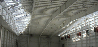
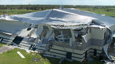
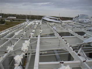
Haag completed a forensic evaluation of four recently constructed airplane hangar buildings which sustained metal roofing damage, as part of a subrogation investigation.

Haag engineers evaluated the design and construction of the roofs at recently constructed airplane hangar buildings.  These buildings near the coast sustained extensive damage to their metal roofs during a hurricane with wind speeds well under what the code required them to withstand. Our analysis revealed significant installation deficiencies including missing fasteners at critical edge zones and fasteners that were incorrectly anchored into the soffit instead of the eave purlins.  Analysis of the design revealed inadequate uplift resistance in two of the three wind zones.  Our research also revealed that the manufacturer had later recognized a problem with this roof system in high wind areas following the 2004 and 2005 hurricanes and developed a more robust system to address these issues, after these roofs had been constructed and failed.  Haag presented compelling evidence during mediations that led to the resolution of the subrogation phase.

airport-hanger-roof-damage

Brick Veneer Collapse

brick-veneer

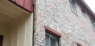
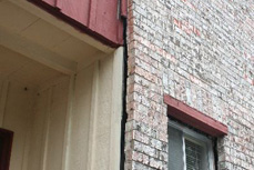
Haag Engineering was asked to determine cause of exterior masonry veneer damage, and when that damage occurred.

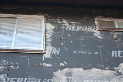
Haag Engineers inspected an apartment building on two occasions: first to document the existing condition of the brick veneer, and second to document the method of securement of the veneer to the exterior wall as the veneer was removed from the building. The second inspection provided the basis for our opinion that there were an inadequate number of brick ties to support the veneer causing lateral deflection from the wall. We researched the local building code at the time of original construction and confirmed that the veneer was not installed per code. Veneer movement had occurred over time since the building was constructed.

brick-veneer-detail
brick-veneer-2

Collapse on The Set of Titanic

Titanic-Image

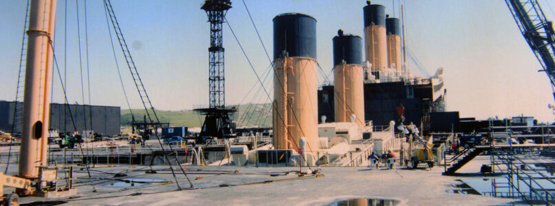
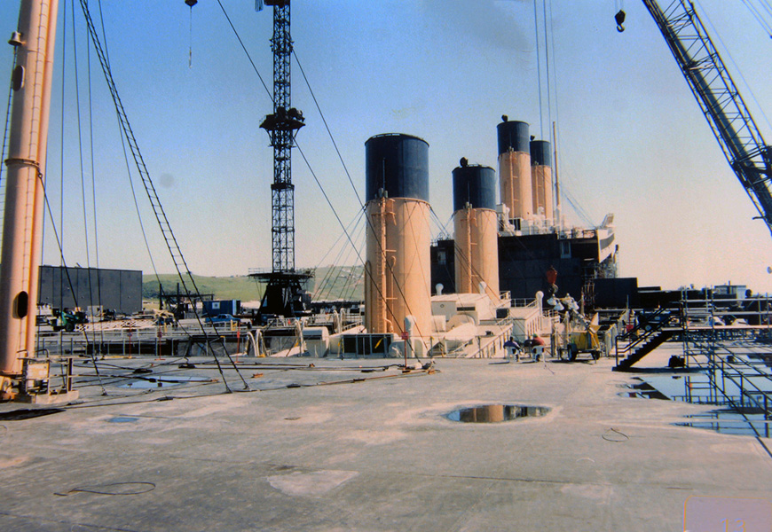
Haag Engineering Co. consultants were called to the set of the feature film Titanic to perform an inspection following collapse of part of the set.

In February 1997, Haag Engineers were called to the movie set of the feature film Titanic. Ironically, the 90% scale movie set “sank” near the end of filming. The overall model was a steel frame mostly on dry land that was clad with metal panels to look like a ship. To simulate sinking, the bow was progressively tilted into a pool of water by lifting the entire frame and cutting the columns shorter. For the final scenes, the bow section was a separate set, supported by a series of hydraulically-actuated cables and buoyant foam blocks to make the set appear to float while it was being actuated with the cables. (The flotation blocks could not support the weight.) Unfortunately, a series of modifications needed to improve realism resulted in support failures that let the set sink, interrupted filming, left expensive actors and crews idle, and impacted actor confidence in the structure.

The set of Titanic was housed in a brand-new movie studio, complete with a 17 million gallon water tank (the largest ever constructed) on the coast of Rosarito, Mexico. When the film Titanic was released on December 19, 1997, it was the most expensive movie ever made, costing about $1 million per minute of screen time, exceeding $200 Million. (IMDB.com)

“The problem with the set, at the time I arrived, was that they weren’t really certain what had occurred. All they knew was that it was suspended on cables and flotation blocks at the time that it partially collapsed,” said David Teasdale, P.E., Haag Principal Engineer and VP of Engineering Services. “We had to wait a day while the tank was drained, and we took that time to learn the structure, review plans, talk to the designers and users, and tour some of the other sets where filming continued.  The set had broken and partially sank once earlier, and different groups had different concerns about why.  A film production is unique, in that, down days are factored into the film schedule.  Therefore, the business interruption claim is not confirmed until filming is complete and it is known that the accident actually cost any time.  In this case, the actors and crew were costing many thousands of dollars per day.”

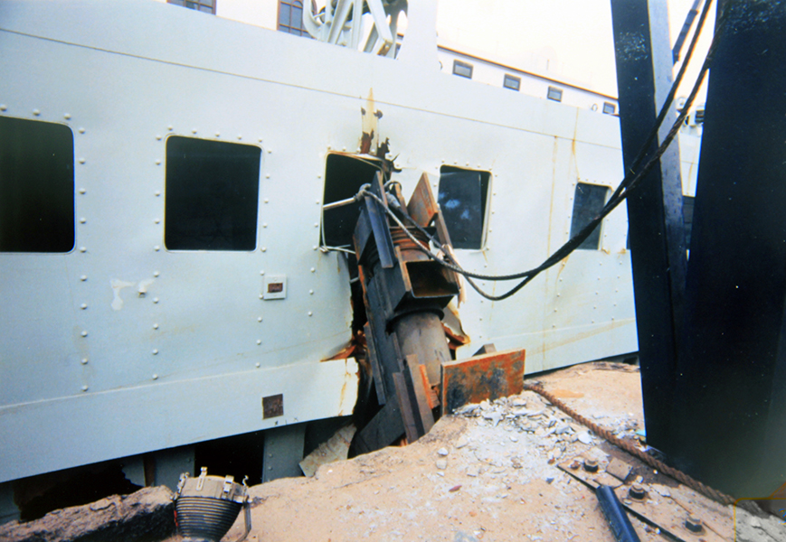
“Once the tank was drained, we observed that one support leg had broken loose, kicked out, and allowed the set of the ship to tilt into the pit of water.  In essence, more flotation blocks were called for to improve the buoyant look during filming, and there was only so much room under the set to fit them in.  When the extra blocks were added, the cross braces had to be moved higher on the columns.  The structural contractor had completed his work and left the site, so he subcontracted a local welding crew to do the work from an engineer’s plan.  One main support leg had pulled loose due to a bad weld, and the bad weld was one of many.  The solution was pretty simple. First and foremost, the repair needed to be implemented quickly, because time is money, and secondly, since it had failed once before, we needed to restore trust in the set. Therefore, Haag Engineers were included in the repair oversight.  Subsequently, we were asked to assist characterizing the failures to help others define whether they met the definitions for insured delays.  Haag also testified at the subrogation arbitration.” 

A forensic consultant needs to do more than simply identify the problem, and Haag Engineering has a long history of identifying problems large and small, helping with the solution, communicating the information needed to a variety of parties with different interests, and providing the engineering perspective needed for others to resolve any resulting disputes.

by David Teasdale, P.E., Principal Engineer & VP of Engineering Services

David Teasdale specializes in structural evaluations, earthborne and airborne vibrations, geotechnical evaluations, general civil engineering, and wind and related storm effects.  He is the primary author and presenter of a Haag classroom seminar course on earthquake damage assessment and Haag’s California Earthquake Adjuster Accreditation course.
Titanic-image-cropped
Titanic-Damage

Custom Wheel Display Accident

wheel-display

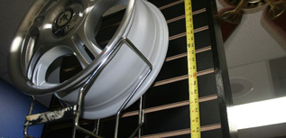
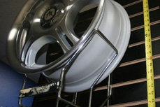
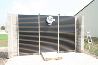
Haag Engineering was asked to determine the likely cause of an accident involving a custom wheel display, and to evaluate the displays adequacy and safety.

Haag Engineering reviewed numerous depositions, examined the involved auto parts store, monitored Plaintiff’s expert’s deposition, examined Plaintiff’s expert’s exhibit, examined custom wheels and holders similar to those used in the involved display, and tested an exemplar custom wheel display to determine the wheel’s susceptibility to external forces and displacement from the holder.

wheel-display-detail

Foundation Movement

stemwall-crack

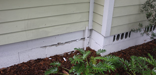
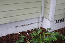
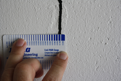
Haag evaluated possible residential ground subsidence and structural damage at a residence.

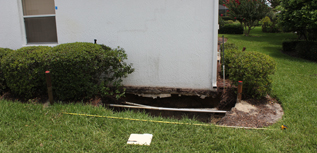
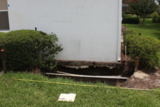
Haag was asked to inspect a residence with cracks in the exterior stemwall, interior walls, and ceiling. The house was wood-framed, built in 1940, and had a combination stemwall and pier and beam foundation. It was located in the Tampa Bay area, where sinkholes are common. Haag performed a structural inspection, floor elevation survey, ground penetrating radar survey, foundation excavation and inspection, soil borings, and laboratory testing. Our investigation revealed that the damage was not caused by a sinkhole, but rather was due to a layer of buried peat as much as 11 feet thick. Peat is highly compressible and will continue to compress over time as the organic material continues to decay. Haag recommended underpinning the home’s foundation.

stemwall-crack-detail
stemwall-2

Grain Elevator – OSHA Citation

grain-elevator

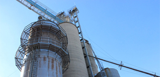
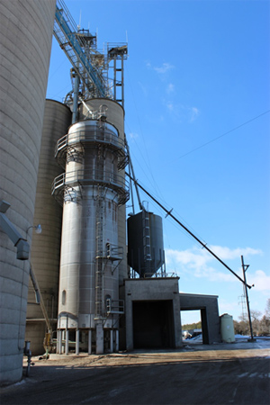
Haag was asked to evaluate design and installation of a cross-flow grain dryer at an Ohio grain elevator, and address the merits of an OSHA citation related to installation and safety, & evaluate compliance with 29 CFR.

A natural-gas fired, choke-fed, cross-flow dryer was originally installed by the manufacturer in 1997 and had remained substantially unchanged. After a brief visit, OSHA issued citations which stated that the involved dryer was not equipped with “controls that automatically stopped the incoming grain to the dryer when a high temperature condition was detected.” Further, OSHA added that “it was clear the equipment [had] the necessary components to be installed to meet the standard… but it was discovered that the alarm sensor… was never installed.”

Haag reviewed installation and operator manuals provided with the grain dryer and determined that the involved dryer could be installed in one of two configurations – a choke-fed configuration and a reversing-slide gate configuration. For the former, a positive shutdown mechanism for the incoming grain elevator leg was not recommended by the manufacturer. Grain flow into the dryer was stopped by shutting down the discharge metering system during a high temperature alarm, causing the incoming grain to bypass the dryer spout and return to storage. Since the automatic shutdown of the discharge metering system effectively stopped the flow of grain into the dryer, we concluded that the automatic shutdown complied with the requirements of 29 CFR 1910.272. Site visits by Haag and the dryer manufacturer independently verified that all required sensors and controls were properly installed on the involved dryer.

Further, Haag reviewed national consensus standards for emergency shutdowns published by the National Fire Protection Association (NFPA). A key distinction between the NFPA and 29 CFR 1910.272 was that the NFPA required the sensors to “stop the flow of product out of the dryer” while 29 CFR required sensors to “stop the grain from being fed into the dryer.” Haag Engineering evaluated the merits of each standard using Failure Mode and Effects Analysis and other techniques and concluded that the NFPA standard provided greater protection from the anticipated hazards than 29 CFR 1910.272. According to Appendix A of 29 CFR 1910.272, compliance with a national consensus standard that provides equal or greater protection than 29 CFR 1910.272 is considered compliance with the corresponding requirements.

We published a report addressing the alleged installation issues and safety requirements of both 29 CFR and the NFPA. Our analyses had shown that the involved dryer complied with both standards. The matter was ultimately resolved after all citations against the grain elevator were removed

full-grain-elevator

Grain Explosion Evaluation

explosion-ruins

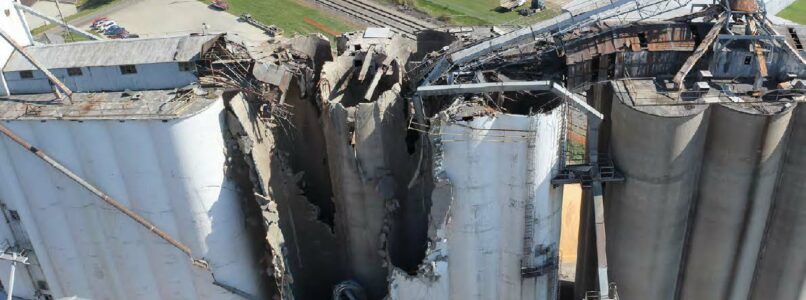
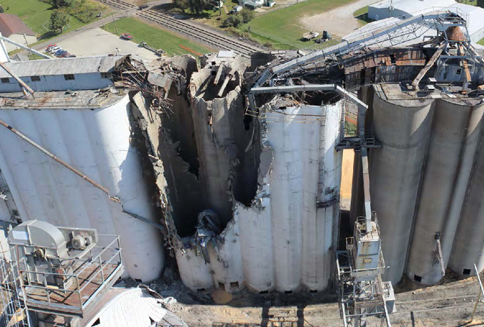
A large grain dust explosion occurred at a grain company facility. The explosion severely damaged three connected silos and injured six workers, as employees were loading rail cars when the explosion happened, and sections of the bins toppled onto the rai.

On August 13, 2014, a large grain dust explosion occurred at the Coshocton Grain Company facility in Coshocton, Ohio. The explosion severely damaged three connected silos and injured six workers. Employees were loading rail cars when the explosion happened around 4 pm, and sections of the bins toppled onto the rail cars.(1)

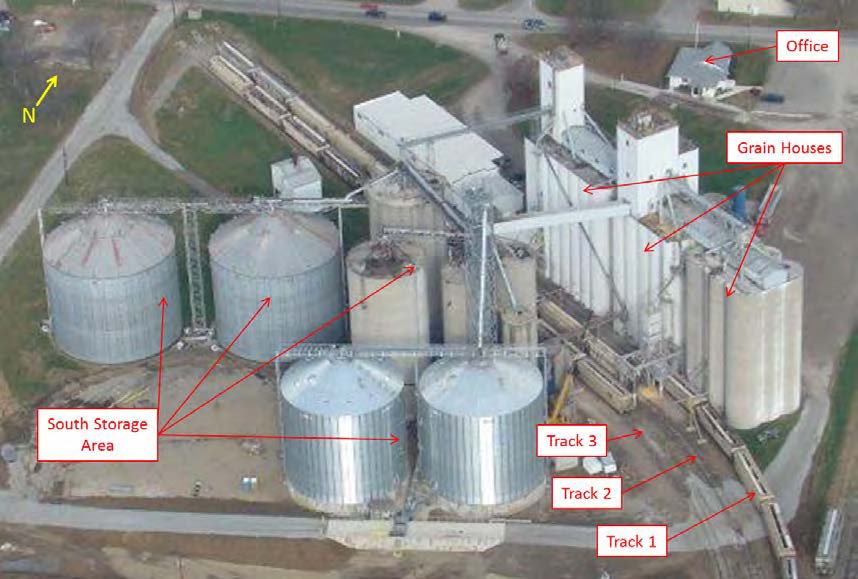
The 60-year-old Coshocton Grain facility was a 2.5-million-bushel capacity grain receiving, drying, and storage facility that included three slip-formed concrete storage houses standing more than 100 feet above grade at the bin deck. A single gallery spanned across all three houses; two of the houses had head houses. A tunnel network connected all three grain houses in the basement, and one of the houses to a truck dump building and to several silos across railroad tracks to the south. South of the railroad tracks were five additional concrete silos, four steel storage bins, and several small buildings.

Seven bucket elevators, 12 drag conveyors, 11 belt conveyors, two screw augers, and one tripper directed the flow of grain throughout the facility. In general, the equipment in the basement and ground-level directed flow of grain away from the dumps and bins, and to the boots of the elevators. Elevated equipment directed flow away from the elevator legs to the various silos, bins, dryers, and load out areas of the facility. There were also three dust collectors, a dryer, a truck scale, and a continuous flow scale.

Haag responded to determine the origin and cause of the explosion, which included coordinating with OSHA representatives and salvage efforts.

The explosion caused a large area of the middle house to blowout and the head house to fall to the ground and damage several railcars and railroad tracks. Haag’s original scope expanded to include documentation of the explosion site using 360° photography and scanning (3D laser scanning), evaluation of structural and mechanical damage caused by the explosion, and a cost estimate of the explosion-related damage. 

SOURCE (1) NO GRAIN, NO GAIN: COSHOCTON GRAIN, FARMANDDAIRY.COM; HTTPS://WWW.FARMANDDAIRY.COM/TOP-STORIES/NO-GRAIN-NO-GAIN-NEARLY-A-YEAR-AFTER-A-DEVASTATING-EXPLOSION-COSHOCTON-GRAIN-IS-COMING-BACK/265567.HTML, JUNE 2015.)

Involved Experts: 
explosion-damage
diagram

Ground Surface Dropout at Residence

Ground-Under-House
Basic Fact Pattern

During a site stabilization, a surface dropout occurred below the residential structure causing additional damage to the foundation and walls.

Investigative Actions Taken

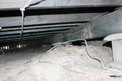
Haag performed a geotechnical subsurface evaluation of a residence related to possible sinkhole activity. Our study of the property involved exploratory drilling and sampling, shallow excavation, a geophysical survey and laboratory testing. Our findings revealed highly weathered limestone at depth and formed cavities and voids from soil raveling associated with sinkhole activity. 

Determinations Made

Haag recommended a program of deep compaction grouting and shallow chemical grouting to stabilize the building pad. During stabilization, several surface dropouts occurred. Haag quickly responded to develop plans for stabilizing the ground and residential structure. Haag monitored the filling of voids below the foundation and slab with a cement slurry and rapidly implemented a grouting program to treat raveled soils and limit property damage.

Involved Expert: 
Ground-Under-House_2
Crack-Measuring

Hoover Dam By-Pass Bridge Collapse

Hoover Dam

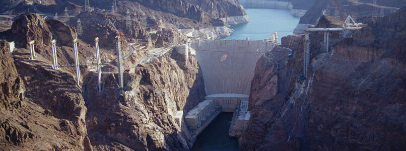
The Hoover Dam’s By-Pass lifting system, a luffing cableway supported by four towers, collapsed during high winds.

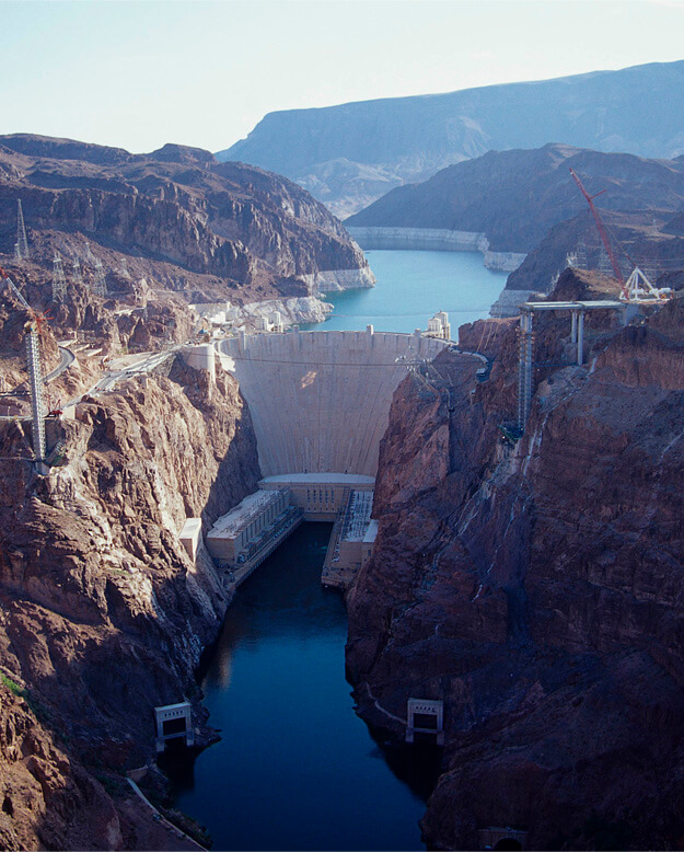
The Hoover Dam By-Pass Bridge was part of the new alignment of U.S. Highway 93 across the Black Canyon between Arizona and Nevada and was located approximately 1,500 feet downstream of Hoover Dam. Total length from abutment to abutment was approximately 1,090 feet.  The structure was the first concrete-steel composite arch bridge built in the United States and includes the longest cast-concrete arch in the Western Hemisphere. The Obayashi Corporation and P.S.M. Construction USA, Inc. Joint Venture (Obayashi/PSM JV) was awarded the bridge construction contract by The Federal Highway Administration (FHWA). HDR Engineering, Inc., and T.Y. Lin International were the bridge design team.

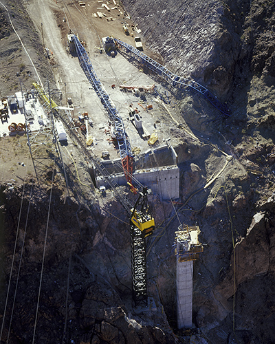
For construction of the bridge, the By-Pass lifting system was a luffing cableway as defined by the American Society of Mechanical Engineers (ASME) B30.19 – Cableways. Four lattice towers, each approximately 330 feet tall, were erected on either side of the Colorado River immediately south of the Hoover Dam. Distance between the opposing towers (span) was approximately 2,500 feet. The two cableways extended parallel and along the centerlines of the double highway lanes of the new bypass bridge. Each tower could lean (luff) in the north/south direction to provide lifting capabilities for the load block to reach the entire width of each of the double highway lanes. Lower and upper load blocks were supported by a carriage that was positioned along the spanned length by inhaul and outhaul ropes on the track cables (gut lines).

During high winds on September 15, 2006, the Nevada South tower buckled and collapsed.  During the collapse, the falling sections severed multiple support cables of the Nevada North tower causing it to fall to the north.  The resulting collapse of both Nevada towers imparted dynamic loading to the two Arizona towers, causing both to fall westward toward the Black Canyon of the Colorado River.

Haag Engineering Co. was retained to determine factors causative of the collapse and evaluate duties and responsibilities of the parties involved in the design, erection and use of the specialized equipment.  During recovery efforts, Haag assisted in the design/evaluation of a new cableway system, erection and load testing.  The Haag team was assigned to the project from collapse on September 15, 2006 until the connection of the arches in 2010. 

The Hoover Dam By-Pass Bridge was sucessfully completed after this set-back, and officially named the “Mike O’Callaghan–Pat Tillman Memorial Bridge”. Opening ceremonies were held on October 19, 2010. The bridge has been a vital to improving traffic on Interstate 93, between Phoenix and Las Vegas and between the United States and Mexico, ever since.

Hoover Dam
accident-hoover-dam

Hurricane Shelter Collapse

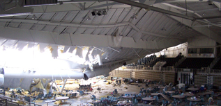
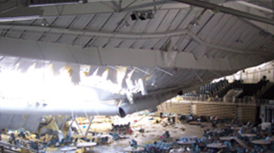
Haag Engineering was asked to determine the cause of collapse of a hurricane shelter, determine responsible party with respect to subrogation, & evaluate the remaining structure with respect to repairability.

The metal building structure was an indoor sport/event arena that doubled as a hurricane shelter.  Approximately 1,400 people had flocked to the shelter for safety before the storm.  The metal roof system peeled away as the storm neared, causing most of the building to collapse.  All 1,400 occupants survived due to their retreat below the concrete bleachers.  Haag Forensic Engineers were called out to determine the primary cause of the collapse, determine who was responsible with respect to subrogation, and to evaluate the remaining structure with respect to reparability.  We examined the structure, stewarded required evidence retained for all parties, and identified building conditions that led to the collapse.  Our conclusions were provided via open forum presentation during mediation.  The accuracy, detail, and reporting of our conclusions in a simple yet complete presentation enabled all parties to quickly understand the facts of the collapse and come to a mutual financial agreement without litigation.  The structure was reconstructed after settlement was achieved.