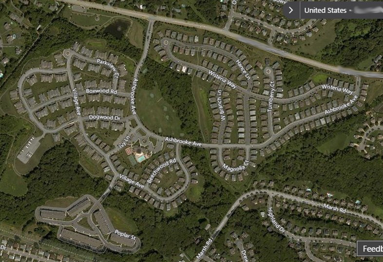
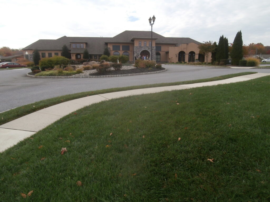
Development of 250 units, including a clubhouse building, townhomes, and single family residences.
Alleged construction defects in the exterior claddings resulting in systemic moisture intrusion and underlying structural damage.
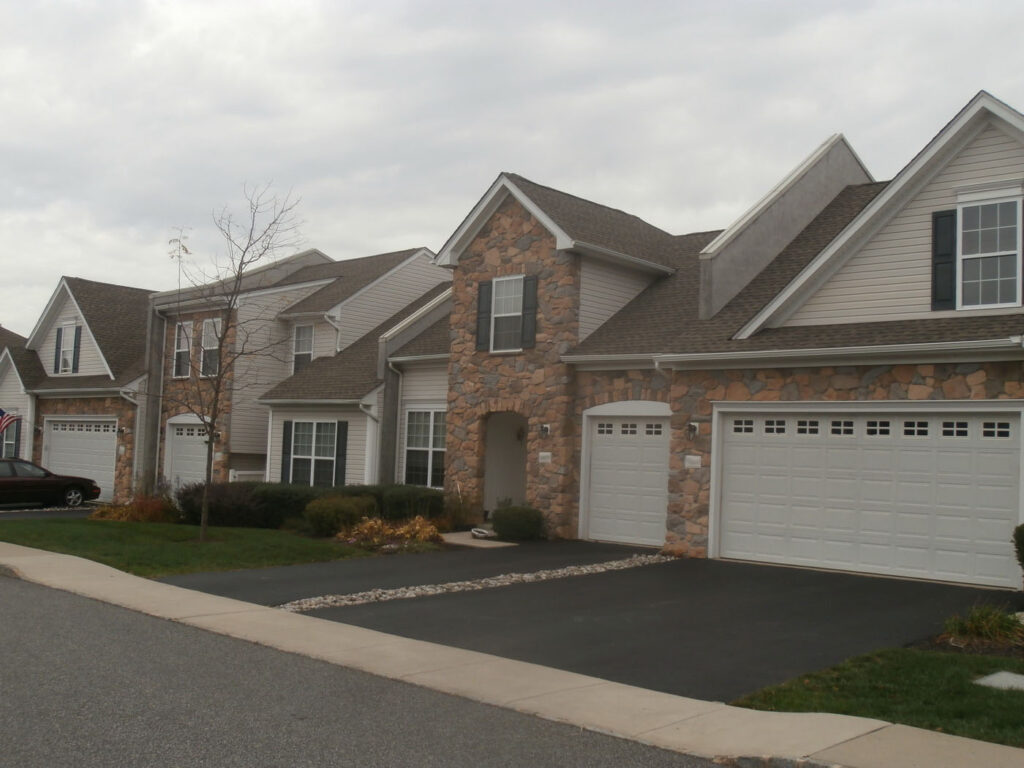
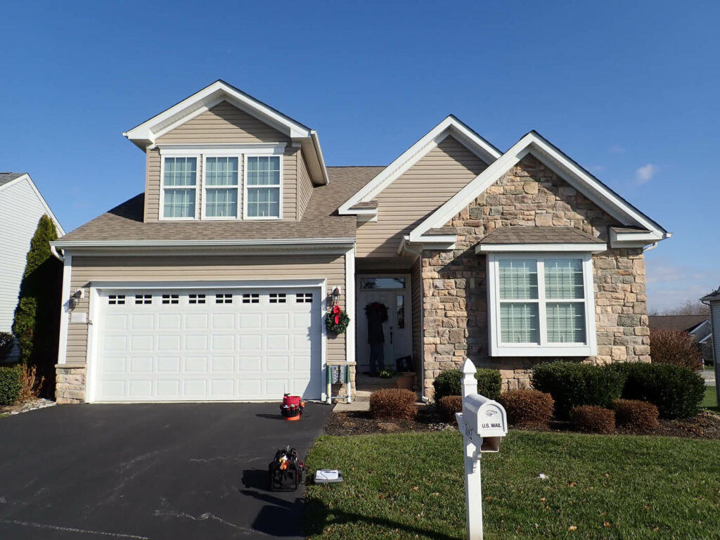
Exterior claddings consisted of combinations of vinyl siding, hardcoat stucco, and adhered stone veneer.
Alleged damages included complete re-cladding of all buildings.
Investigative Sciences Employed
All 250 buildings were visually inspected.
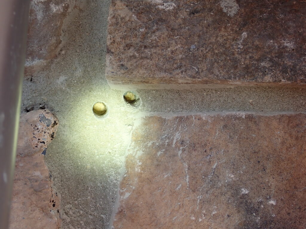
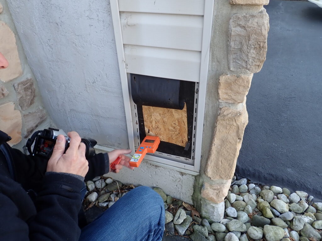
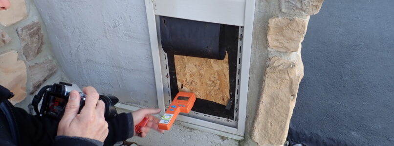
Moisture probe tests were performed on a representative sampling of buildings of each type.
Destructive test cuts were performed and a separate representative sampling of buildings of each type.
Detailed analyses of opposing expert investigational methods were performed.
Comprehensive code analysis was performed across the three building codes represented across the timeframe of construction for the differing phases of the development.
Determinations Made
Actual moisture intrusion was minimal, localized, isolated, and associated with discrete, non-systemic causes.
Complete exterior re-cladding was not required.
A remedial action plan was developed, along with a cost to perform the repairs.
Litigation support services were also provided throughout alternative dispute resolution.
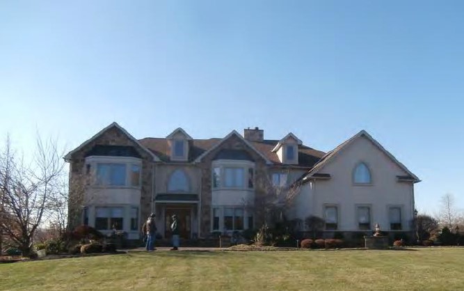
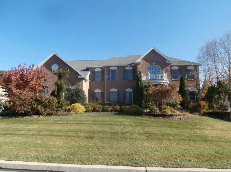
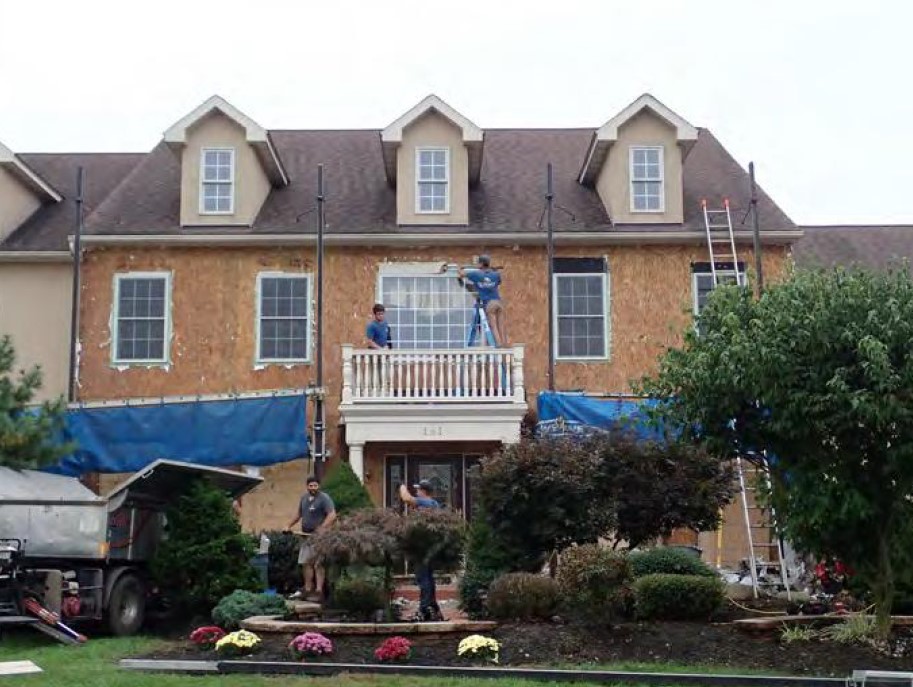
Development of multi-million dollar custom homes, including six homeowners all suing their builder and all of his subcontractors.
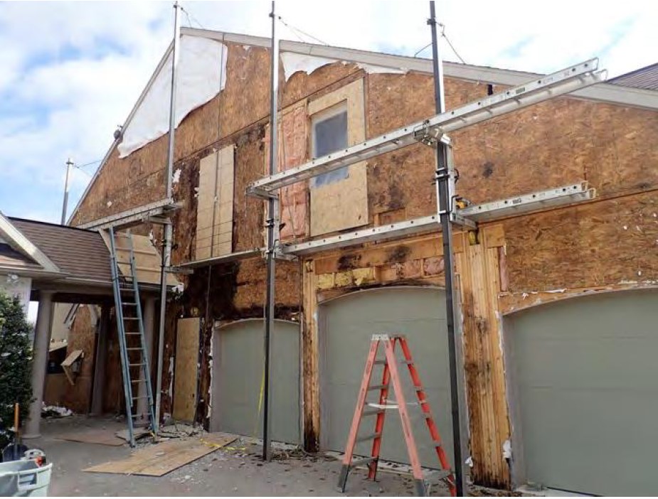
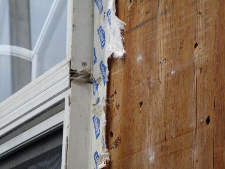
Alleged construction defect in the varying exterior claddings resulting in systemic moisture intrusion and widespread underlying structural damage.
Alleged violation of building codes and consumer protection (fraud) statutes.
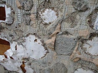
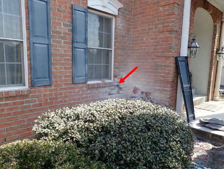
Exterior claddings included six differing combinations of hardcoat stucco, EIFS, wood trim, composite trim, brick veneer, adhered stone veneer, and custom windows.
Alleged damaged included complete re-cladding of all six residences, along with treble damage associated with consumer protection.
Minimal documentation was available from the builder, more than one decade after construction was completed.
First opposing expert passed away, prior to completing his work, causing a second expert to be engaged, who offered slightly differing opinions.
Investigative Actions Taken
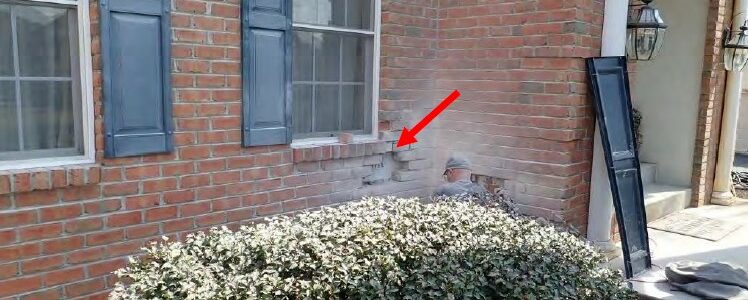
Each residence was inspected inside and out, and destructively tested for moisture intrusion and associated underlying damage.
Interior thermal imaging and temperature and humidity surveys were conducted.
Re-cladding of four residences was observed.
Multiple code analyses were performed across the time periods from the first home to the last one.
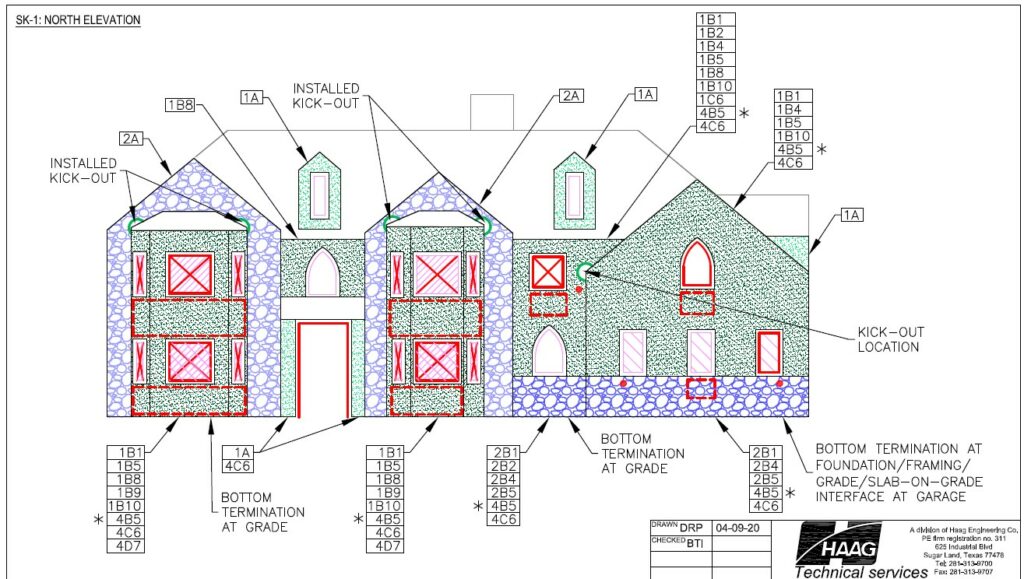
Each home was 3D modeled, with material take-offs performed for individual wall panel.
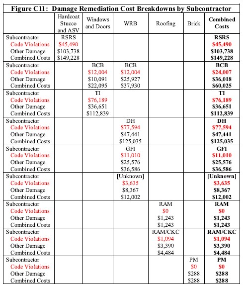
The varying subcontractor structures for each home were reconstructed from the documentation produced by others in the matter.
Detailed causation and code analysis tied each individual wall panel requiring remediation back to the cause(s) of the damage and the specific subcontractors responsible for the same.
Extensive comparative analysis between the two plaintiff’s expert’s opinions, including completion of the training previously performed by the deceased one.
Determinations Made
Construction defects and code violations were variable across the six homes, but none were systemic and widespread.
Some interior damage was associated with maintenance, use, and building operation, rather than moisture intrusion through the exterior claddings.
Remediation of all wall panels on all sides of all homes was not required.
A customized scope of remediation was determined for each home, along with the total costs associated with performing the same.
Diagrams capable of allowing a lay audience to understand both causation and damage distributions were created for each side of each home.
All but two subcontractors were identified, with damages distributions determined for each.
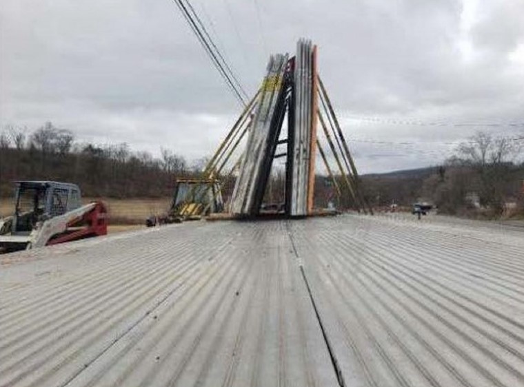
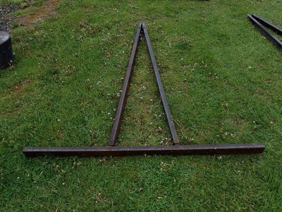
During transportation of marble and granite stone slabs, a structural failure occurred.
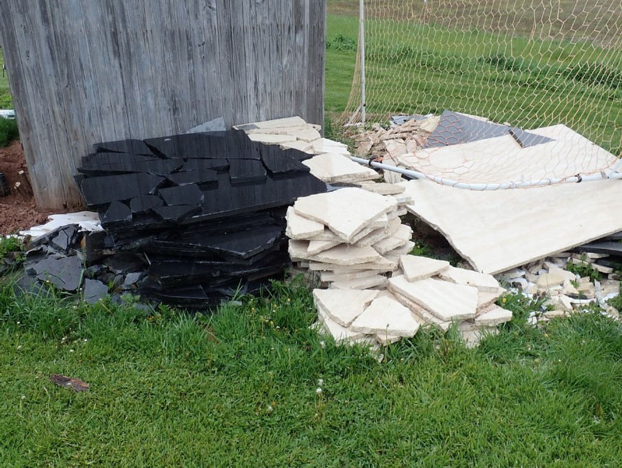
The structural failure caused a complete loss of the marble and granite slabs, along with property damage associated with the spilled debris.
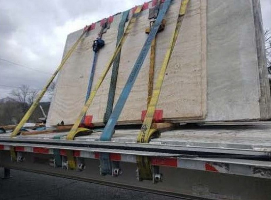
Alleged improper loading, securement, and/or transportation of the stone slabs.
Investigative Actions Taken
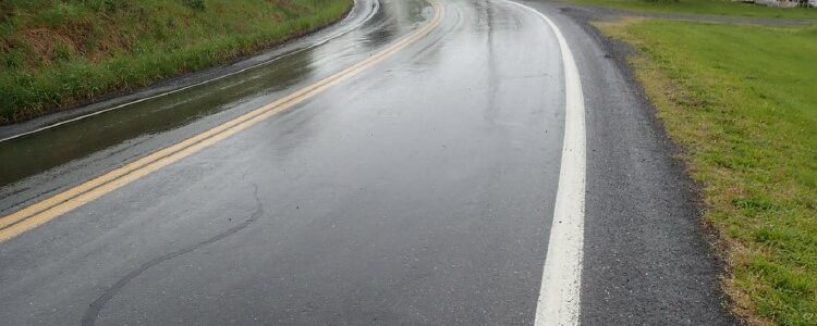
Photos of the accident scene were analyzed, along with the geometric configuration of the actual accident location and the speed and direction of travel of the vehicle at the time of the incident.
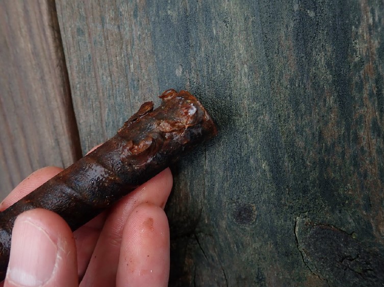
The collected debris from the stone slabs were inspected and analyzed for fracture patterns.
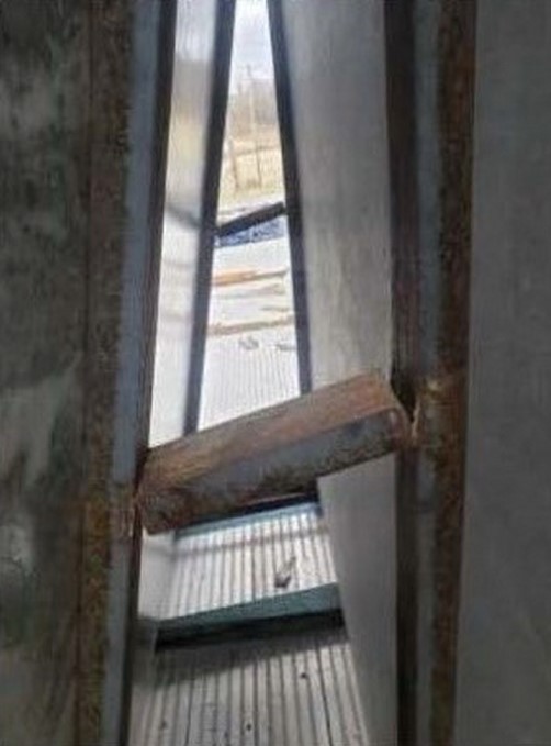
The A-frames were reconstructed from the debris by matching the structural weld failures.
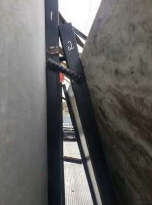
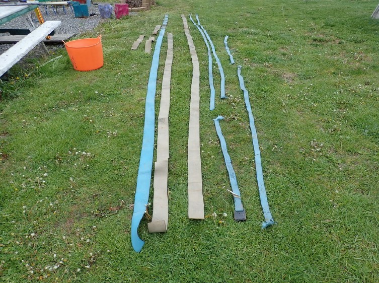
The ruptures in the tie-downs were also matched back to the accident scene photos to determine the original configurations of the A-frames and the securements utilized at the time of the accident.
Determinations Made
The securement and transportation methods utilized were not the cause of the structural failure.
The A-frame racks were provided by the material supplier, not the hauler.
The A-frame racks lacked adequate design, construction, and maintenance for lateral loads, relying solely on increased securement for stability.
The inadequate welds utilized in the A-frame racks design and construction caused the failure, in combination with a lack of adequate inspection and maintenance of the same.
The hauler had increased the securement utilized beyond industry requirements, however, this additional redundancy, beyond normal and usual requirements, did not prevent the accident from occurring.
Effects of Hail-Caused Dents on the R-value of Roof Insulation
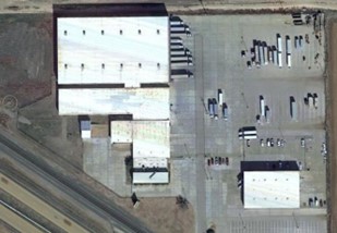
The subject property was a distribution center in Texas with several large buildings covered with single-ply, thermoplastic polyolefin (TPO) membrane roofs installed over various substrates. Concerns were raised regarding hail-caused damage to the roofs and the effects hail-caused dents had on the thermal properties of the insulation. A Haag engineer performed the roof inspection and provided samples of the TPO membrane and insulation substrates to our laboratory to determine if hail-caused dents in the substrates had reduced the insulation R-value.
Figure 1: Overview of property
Four substrate samples were provided to our laboratory. Substrates included various thicknesses of polyisocyanurate insulation (polyiso), including two topped with gypsum coverboard. Table 1 summarizes substrate configurations.
Table 1: Sample Descriptions
Sample
Substrate
1
1/2-inch gypsum coverboard over 3-1/2 inches of polyiso
2
4 inches of polyiso
3
2 inches of polyiso
4
1/2-inch gypsum coverboard over 2-1/2 inches of polyiso
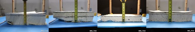
Figure 2: Samples 1 through 4 (left to right)
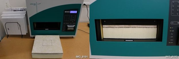
Each substrate sample contained a hail-caused dent centered on the sample. Laboratory personnel prepared each sample for R-value testing by conditioning in a laboratory oven to remove any residual moisture (absorbed humidity) and trimmed the samples to fit inside our heat flow meter (HFM), which is used to perform ASTM C518 – Standard Test Method for Steady-State Thermal Transmission Properties by Means of the Heat Flow Apparatus. Samples were then tested to determine their baseline R-values.
Figure 3: Sample 3 prepared to insert into the HFM (left) and inside the HFM (right)
Test parameters were chosen such that the bottom of each sample was in contact with a cold plate set at 75 degrees Fahrenheit and the top surface of each sample was in contact with a hot plate set at 145 degrees Fahrenheit. These temperatures were selected in accordance with ASTM C1058 – Standard Practice for Selecting Temperatures for Evaluating and Reporting Thermal Properties of Thermal Insulation because they represent in service temperatures of a roof on a hot summer day (upper plate) and a conditioned space below the roof (lower plate).
After baseline R-values were measured, a single dent was added to each sample that was similar in size and depth as the existing hail-caused dents and the R-values were remeasured. Test results are summarized in Table 2. The measured R-values after denting were then compared to the baseline R-values. Review of the measured R-values revealed the differences in R-value in the dented configurations versus baseline values for each sample fell within the accuracy of the HFM, which is +/- 2%.
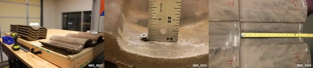
Figure 4: Samples 1 through 4 (left to right) after adding dents
Table 2: Measured R-values
Sample
R-value (Baseline)
R-value
(After Denting)
Difference (percent)
1
12.62
12.48
-1.1
2
16.05
16.05
0.0
3
8.76
8.75
-0.1
4
11.07
11.05
-0.2
An additional consideration, is the R-value measurements taken within the HFM are made within a 4-inch by 4-inch region (metered region) in the center of the HFM. Also, one dent in the insulation is the smallest number of dents that can be measured for comparison. One square of roofing (100 square feet) is 900 times larger than the metered region within the HFM. For this reason, the differences in R-values listed in Table 2 represent a hail dent frequency of 900 hail-caused dents per square. The engineer that performed the roof inspection reported between two and seven hail-caused dents per square in the various substrates. Consequently, the hail-caused dents had no measurable effect on the R-value of the insulation.
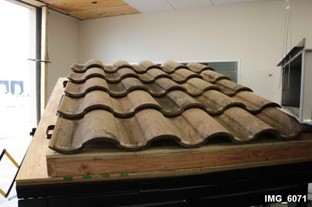
The subject property was an apartment complex in Florida. Roofs were covered with Spanish-profile, concrete roof tiles. Concerns were raised regarding wind-caused damage to the roof tiles and specifically, what minimum wind speed could potentially displace the tiles. An inspection of the roofs was conducted by an outside roof consultant (non-Haag).
The client provided exemplar roofing tiles to our laboratory and detailed the tile installation at the site. Tiles were installed atop plywood roof decking, supported by wood battens, and mechanically attached with 2-1/2 inch long screws. Test panels were constructed, and tiles were installed to replicate tile installation at the property.
Figure 1: Tiles installed on a 5-corse test panel
Figure 2: Tile installation including fastener head stand-off and tile exposures
Tiles were tested in substantial conformance with ASTM D3161 – Standard Test Method for Wind Resistance of Steep Slope Roofing Products (Fan-Induced Method). Test panel configurations were modified as permitted by ASTM D3161 to develop additional information, including variations in slope angle, orientation to the wind stream, and fastened condition. A summary of test configurations is provided in Table 1.
Table 1: Tile Test Configurations
Fasteners
Test No.
Deck Slope
Orientation to Wind
Stream (degrees)
Field
Top Course
1
2:12
0
A
B
2
4:12
0
A
B
3
4:12
30
A
B
4
4:12
60
A
B
5
4:12
0
C
B
A
one screw with 1/4-inch stand-off
B
one screw flush with tile surface
C
no fasteners in field, bottom course left with condition A
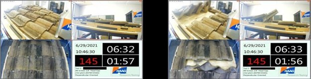
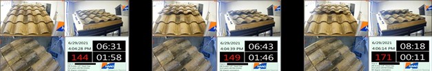
Our wind generator was programmed to ramp to 40 miles per hour (mph) in 60 seconds, then linearly ramp to 170 mph over 390 seconds (6-1/2 minutes), giving an average ramp speed of 10 mph every 30 seconds after the initial 60 second ramp. The wind generator program was manually terminated if/when a failure condition was reached. Tests were recorded using three video cameras in the test room, including an overhead view, a side view, and an angular view, to visually document the effects the wind stream had on the tiles. Wind speed in miles per hour (mph) was superimposed on the video stream providing a real-time correlation between wind speed and test conditions.
Table 2: Test Results
Wind Speed at Critical Moments (mph)
Test No.
First Tile Movement
Field Tile Lift
Field Tile Displacement
Lift-to-Displacement Differential (mph)
1
143
145
145
0
2
141
147
147
0
3
137
145
158
13
4
131
144
149A
5
5
124
138
139
1
Note A:
Tiles lift, shift, and hold, but do not separate from deck at max speed
Figure 3: Test 1 screen shots before lift and after failure (left to right)
Figure 4: Test 2 screen shots before lift and after failure (left to right)
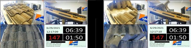
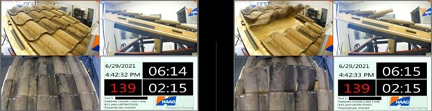
Figure 5: Test 3 screen shots before lift, start of failure, and after failure (left to right)
Figure 6: Test 4 screen shots before shift, start of shift and maximum shift (left to right)
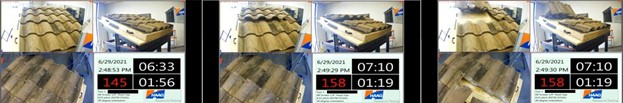
Figure 7: Test 5 screen shots before lift and after failure (left to right)
Testing demonstrated tiles installed in the same manner as they were at the subject property could be displaced by wind speeds of 147 mph and unfastened field tiles could be displaced by wind speeds of 139 mph. Testing also showed wind approaching from different angles (offset by 30 degrees and 60 degrees) would have minimal effect on tile performance, requiring slightly higher wind speeds to displace tiles. Importantly, testing also showed that wind speed sufficient to barely lift the tiles would rapidly displace the tiles. This is due to the aerodynamics changing as air is allowed to impinge on the bottom of tile surfaces once lifting occurs.
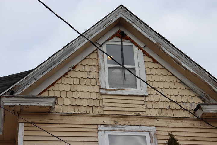
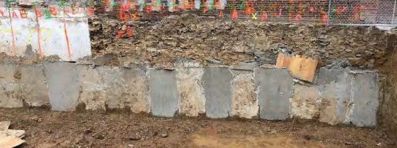
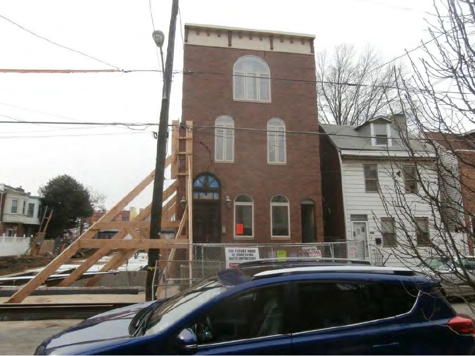
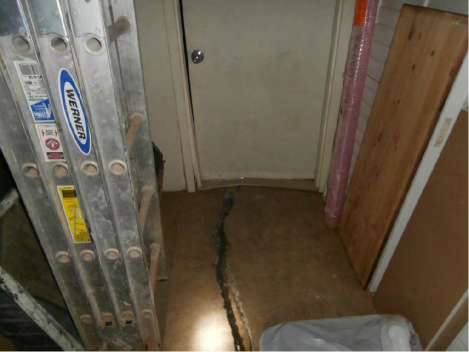
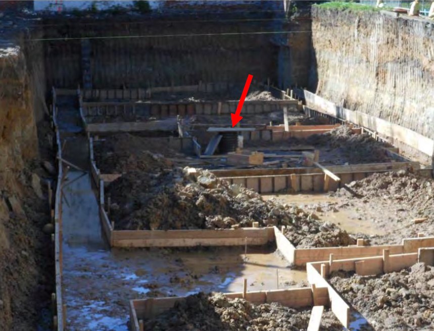
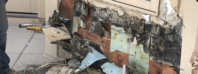
Catastrophic damage to a building adjacent to a demolition and new construction site.
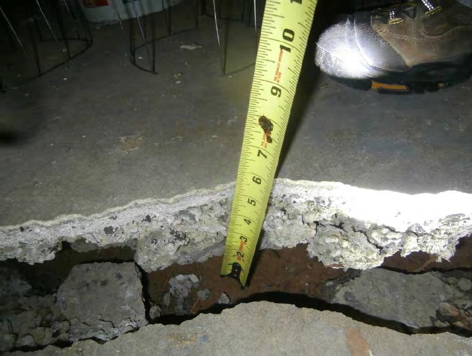
The adjacent building suffered a severe underpinning failure after the demo was completed and the construction was in progress.
The local municipality demolished the adjacent building after condemning it.
The insured underpinning contractor had allegedly performed improper excavation and underpinning, including a lack of dewatering, leading to the underpinning failure.
There were numerous conflicting elements of testimony and documentation amongst the multiple other involved parties warranting further investigation.
Investigative Steps Taken
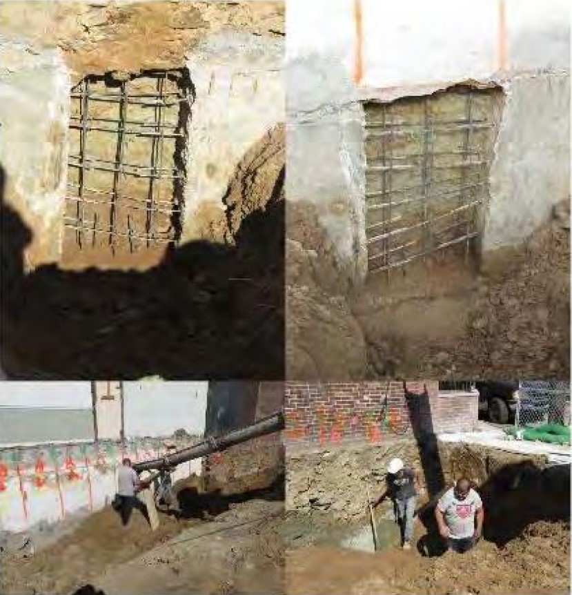
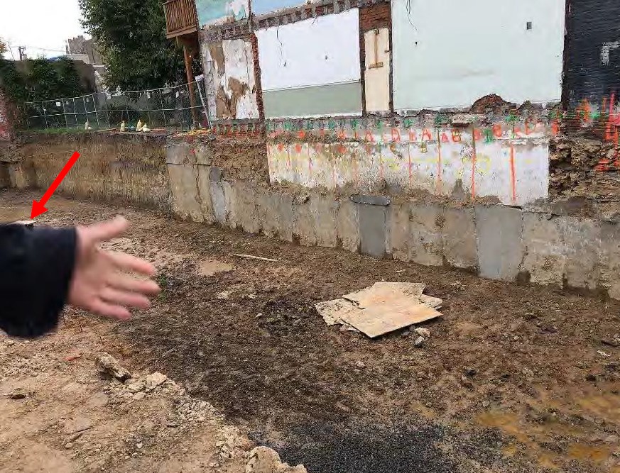
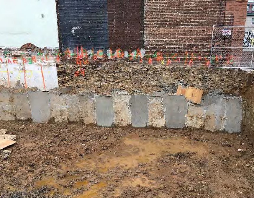
Severely damaged building was inspected, along with the adjacent construction site.
Extensive testimony and documentation was performed, in order to produce a timeline of verifiable facts.
Drawings and geotechnical information were analyzed for appropriateness of the underpinning design.
On-site photos and daily construction logs were analyzed to determine the work actually performed in the field and the timing of the same.
Extensive comparative analysis was performed to determine the truth of the matter.
Determinations Made
The engineer responsible for the design and inspection of the underpinning was practicing engineering outside of his technical competence.
Both the structural and geotechnical design of the underpinning were insufficient for its intended purpose.
The in-field direction provided by the engineer to the underpinning subcontractor directly led to the catastrophic underpinning failure.
The engineer also falsified records submitted to the municipality, resulting in reporting to the local engineering board for disciplinary action.
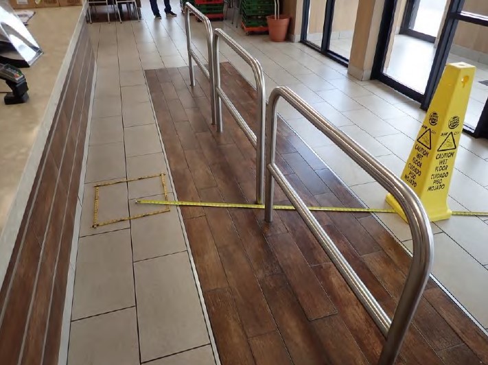
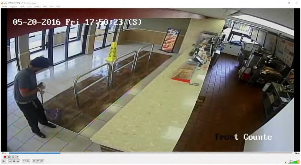
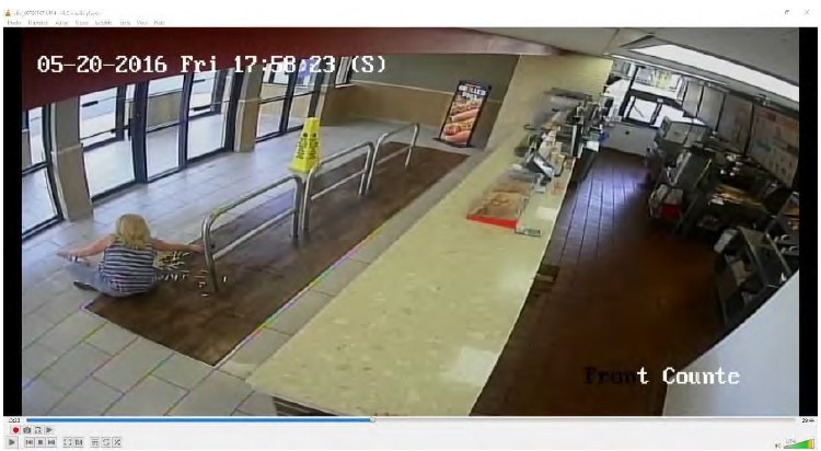
Slip and fall on a recently mopped floor in a fast food restaurant.
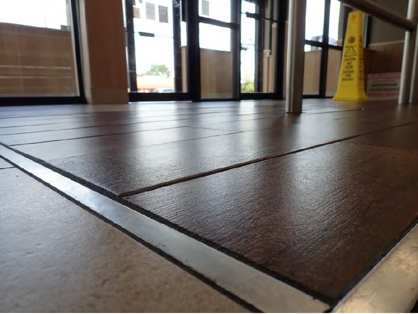
The floor tile involved was allegedly improperly designed, constructed, inspected, and maintained for such a facility.
Specifically, the floor tile lacked adequate slip resistance, when tested wet with a BOT-3000e tribometer.
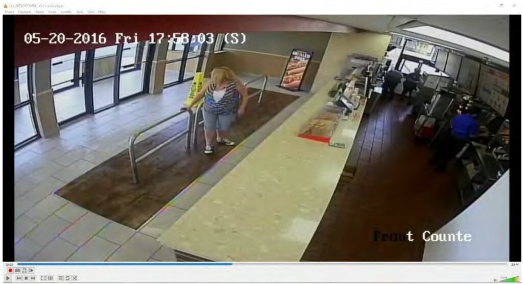
The incident was captured on high resolution video surveillance, along with time both before and after the incident.
It was also alleged that the plaintiff had not been adequately warned about the presence of a wet floor.
Investigative Actions Taken
The details of the incident were extracted from the deposition testimony and documentation of multiple parties.
The video surveillance footage was analyzed for:
The timing of the mopping and the subsequent drying of the floor.
The biomechanics involved in the fall event, as well as the plaintiff’s actions before and after the incident.
The actions of others undertaken at or near the incident location, both before and after the incident.
In the field, the position of the wet floor sign was re-created, after which analysis of the sight lines during all of the Plaintiff’s movements prior to the incident were analyzed.
Measurements were also taken in the field, along with observations of the cleaning equipment and procedures.
Code and construction information was reviewed for the floor tile at issue.
Testing performed by others without our knowledge was reviewed against standards for the same.
Determinations Made
The incident location was mopped eight times less than five minutes prior to the incident, with the “greasy substance” felt by the Plaintiff created by her spilled French fries.
There was no scientifically credible evidence that any improper procedures had allowed the floor to remain “greasy” after it had just been mopped.
The floor tile complied with the applicable building codes and properly applied standards.
The tribometry testing performed by the opposing expert was scientifically invalid, due to a lack of adherence to the standards for the same.
The opposing expert had also performed improper analysis of alternative codes and standards which did not apply.
The Plaintiff had eight separate sight lines where the Wet Floor sign was unobstructed within her field of view, prior to falling reportedly with no knowledge that the floor was wet.
The Plaintiff’s slip event initiated as a result of ill-fitted footwear, combined with an accelerated gait pattern (i.e., hurried walking), resulting in a slip event that was not consistent with the 10 other people shown in the video surveillance footage walking over the same incident location successfully while the floor was still wet.
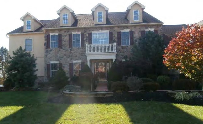
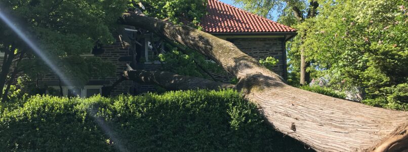
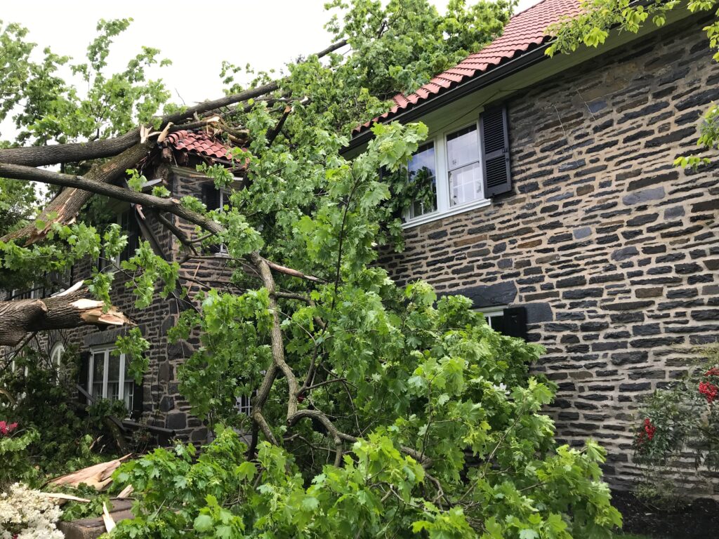
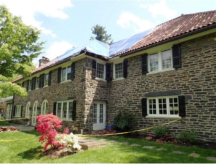
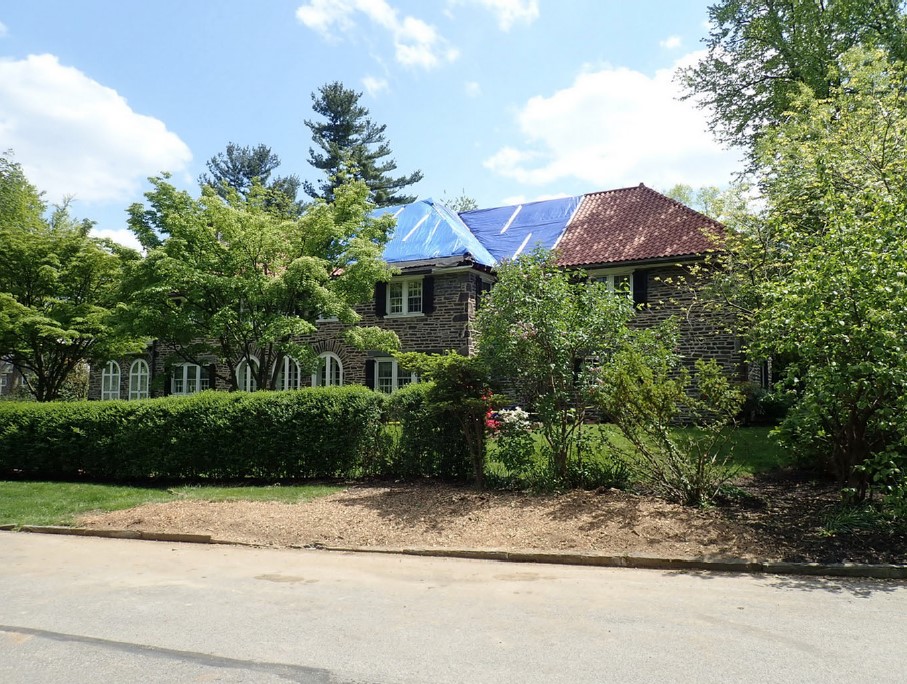
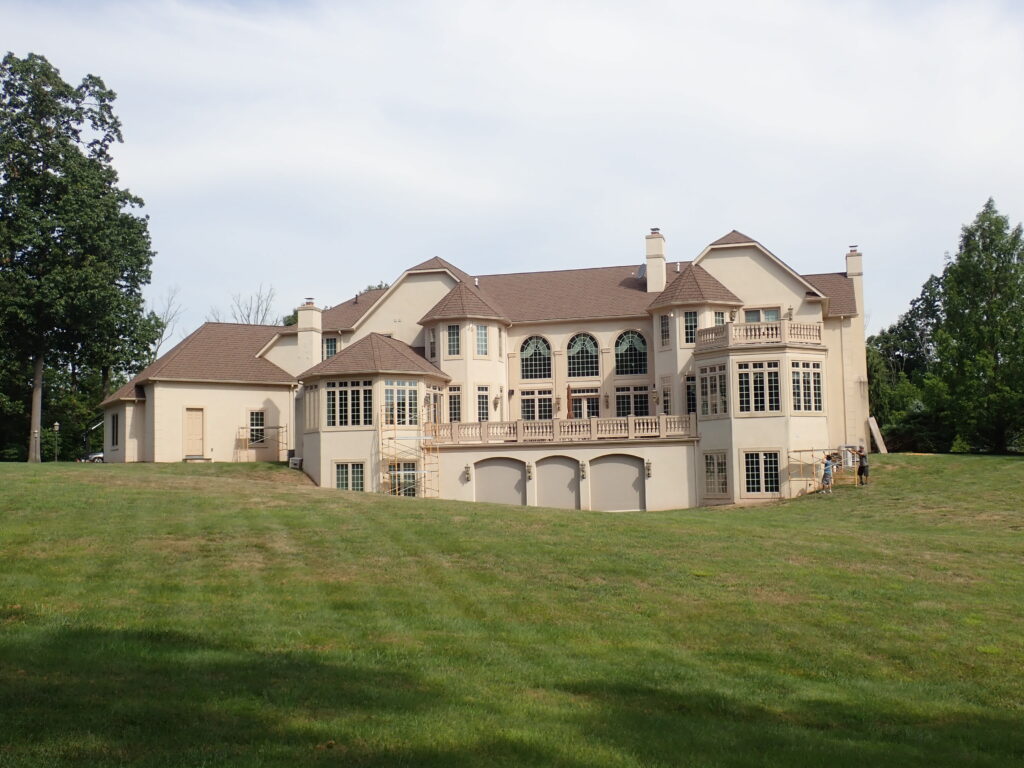
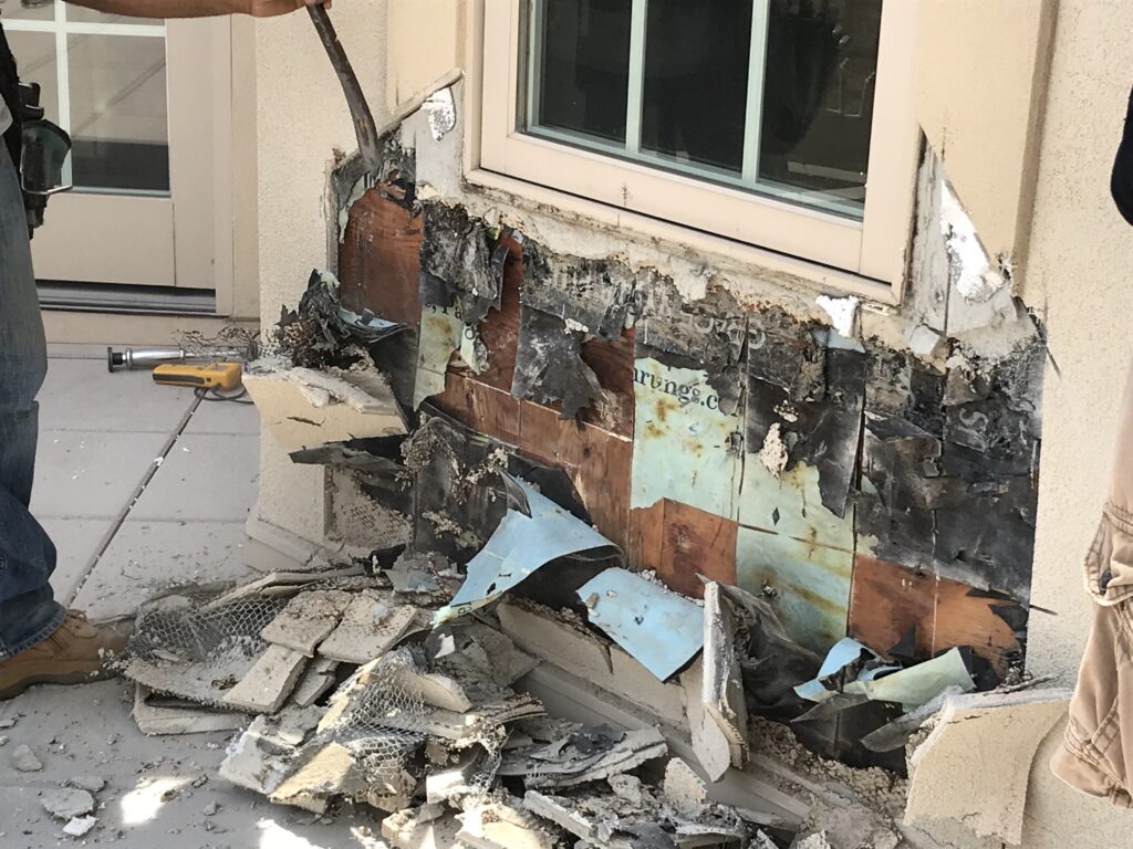
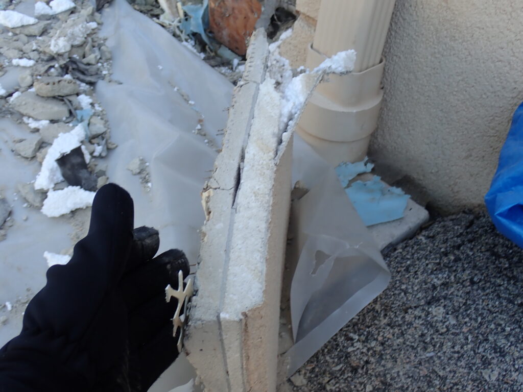
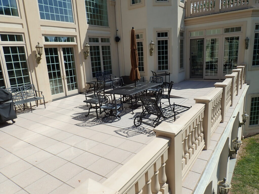
Multi-million dollar custom residence with alleged construction defects in the varying exterior claddings resulting in systemic moisture intrusion and widespread underlying structural damage.
Alleged violation of building codes and consumer protection (fraud) statutes.
Multiple exterior claddings types and custom doors and windows.
Extensive landscaping and post-construction modifications.
Full documentation from the builder of the construction process, materials, and methods.
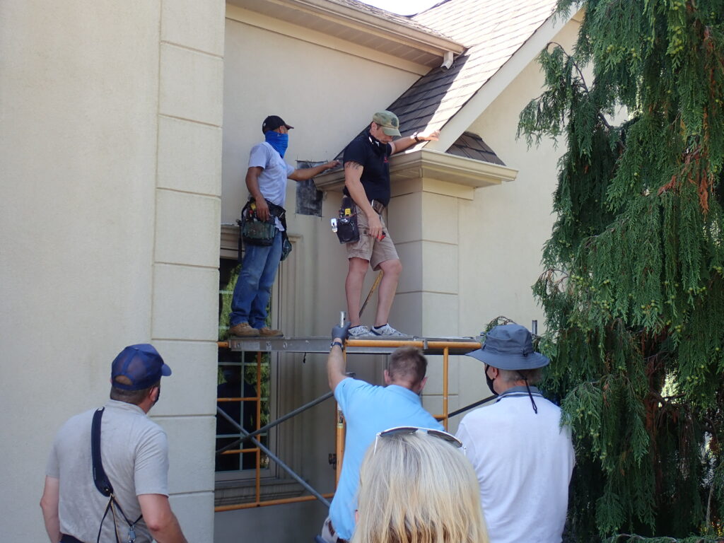
Opposing expert cut 15 holes into the building during multi-party destructive testing.
Investigative Actions Taken
Available documentation was analyzed in detail with regard to each constructed component.
Historic online imagery of the home was used to create a timeline for the post-construction modifications made.
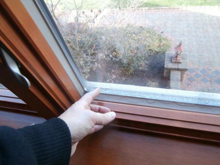
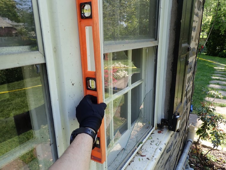
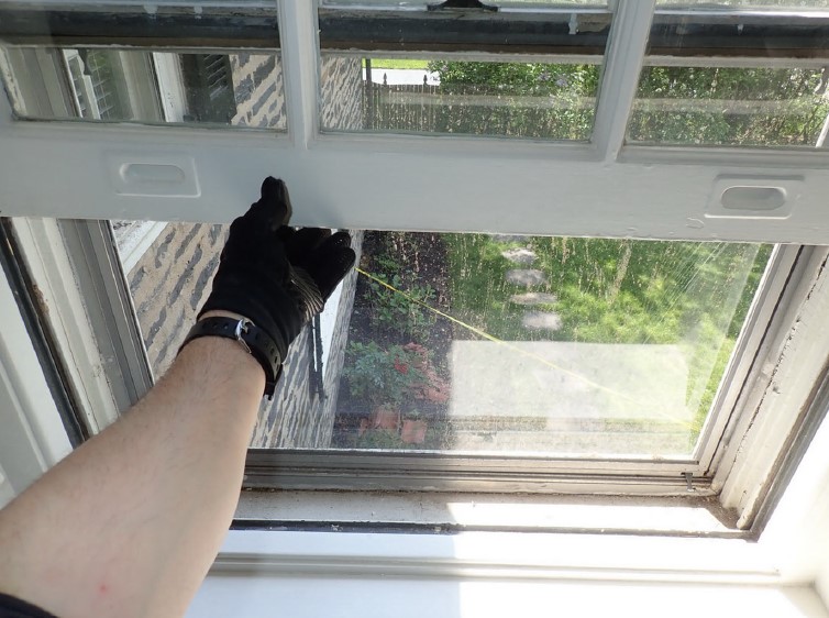
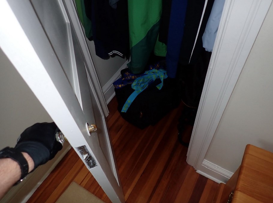
The destructive testing program was observed, with a complete interior and exterior inspection completed.
Observation was also provided during storm damage repair work performed after the destructive testing had been completed.
Determinations Made
Opposing expert did not properly understand how the construction and post-construction modifications were executed, leading to significant confusion amongst the parties.
Construction defects, to the extent they existed, were related to deficiencies in the code requirements and building science understandings of the potential performance of the installed materials within the local climate at the time of construction.
Subsequent building science research has proven that these materials cannot physically perform when constructed as they were required to be at the time of construction, leading to specific code changes made since then.
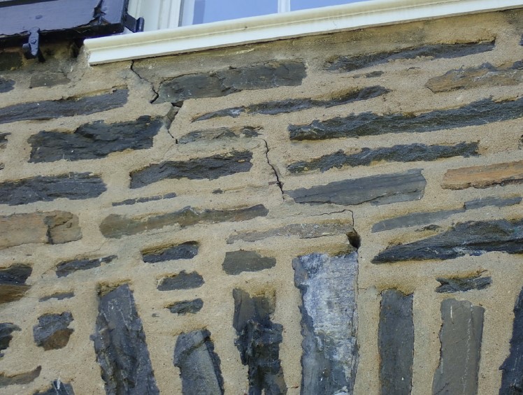
Both the moisture intrusion, and the underlying damage, were associated with localized and isolated causal factors, rather than widespread and systemic ones.
Re-cladding of the entire residence was not required, and this was already known from testing previously performed, without the need for the excessive destructive testing.